


| Issue |
Sci. Tech. Energ. Transition
Volume 81, 2026
Innovative Strategies and Technologies for Sustainable Renewable Energy and Low-Carbon Development
|
|
|---|---|---|
| Article Number | 18 | |
| Number of page(s) | 14 | |
| DOI | https://doi.org/10.2516/stet/2026032 | |
| Published online | 22 July 2026 | |
Regular Article
Enhanced battery energy storage damping controller for alleviation sub-synchronous resonance in wind power plants
1
Department of Electrical Engineering, Delhi Technological University, Delhi, 110042, India
2
Electrical Engineering Department, Government Engineering College, Siwan, Bihar, India
3
Electrical and Electronics Engineering Department, Krishna Institute of Engineering and Technology (KIET), Ghaziabad, India
* Corresponding author: This email address is being protected from spambots. You need JavaScript enabled to view it.
; This email address is being protected from spambots. You need JavaScript enabled to view it.
Received:
20
April
2025
Accepted:
18
June
2026
Abstract
The study introduces an enhanced damping controller using a battery energy storage system to mitigate sub-synchronous resonance in transmission lines equipped with static series compensation associated with a doubly fed induction generator-based wind power facility. This project aims to create a resilient damping controller that ensures stability under diverse operating situations and to refine controller settings using an innovative optimization technique for enhanced damping efficacy. In contrast to traditional damping controllers, the suggested controller incorporates an additional damping signal integrated into the d–q axis of the control channels. The auxiliary damping signal utilizes angular speed deviation, obtained by a large-area measuring method, as its input signal. A hybrid method integrating eigenvalue analysis with an advanced particle swarm optimization technique is used to optimize damping performance across diverse operating situations by determining the best gain coefficients. The variability of wind speed and fluctuations in series compensation levels are assessed to determine the resilience of thef proposed controller in real-world and extreme circumstances. Time-domain simulations were conducted in MATLAB/Simulink to assess their efficacy. The findings confirm that the proposed upgraded controller successfully stabilizes all previously unstable system modes at wind speeds of 7 m/s, 9 m/s, and 11 m/s, as well as at compensation levels of 40%, 55%, and 60%. The suggested controller demonstrates enhanced damping performance and elevated damping coefficients relative to conventional damping controllers, signifying increased stability and resilience across various operating conditions.
Key words: Battery energy storage systems (BESS) / DFIG / Damping controller / Sub-synchronous resonance (SSR) / Fixed series compensation
© The Author(s), published by EDP Sciences, 2026
 This is an Open Access article distributed under the terms of the Creative Commons Attribution License (https://creativecommons.org/licenses/by/4.0), which permits unrestricted use, distribution, and reproduction in any medium, provided the original work is properly cited.
1. Introduction
The energy transition to renewable power sources is greatly aided by the wind power system’s explosive global expansion. Global wind capacity rose by 117 GW in 2023, and by 2025, it will have surpassed 1,000 GW. Approximately 75 GW of offshore capacity and over 106 GW from onshore projects make up this increase, with China leading the way with significant additions from the US, Brazil, Germany, and India [1]. Due to its economic benefits, capacity to independently manage both active and reactive power, and ability to operate at varying speeds while keeping a constant grid frequency, the Doubly Fed Induction Generator (DFIG) has become a frequently used solution in this industry [2]. The fact that wind farms frequently occur distant from the load areas where power demand is greatest presents a significant technological challenge. Compared to more advanced FACTS devices, Fixed Series Compensated (FSC) transmission lines offer an affordable way to improve the ability to transfer power over such long distances; however, their integration with DFIG-based systems can result in an important risk of Sub-Synchronous Resonance (SSR) [3]. The turbine-generator shaft system may experience severe torsional oscillations as a result of this phenomenon. Its severity is shown by several real-world accidents, such as those documented in Texas (2009) and Hebei (2012), when generator tripping and shaft damage were noted [4]. These incidents underscore the critical need for precise modeling, analysis, and the creation of efficient damping techniques to reduce SSR in wind farms.
Simultaneously, the increasing integration of inverter-based resources has significantly reduced total system inertia, resulting in a new grid code need for wind farms to provide ancillary services, such as frequency support, which is often accomplished by droop control [5, 6]. Recent research, however, reveals some important conclusions: the wind turbine may suffer from the same frequency support mechanisms. Incorporating droop control in DFIG-based systems may cause torsional oscillations in the turbine drivetrain, which might shorten the life of important parts like the gearbox, according to Chiu et al. [6]. This presents a difficult trade-off: whereas frequency assistance is required by grid standards, providing it may inadvertently jeopardize the wind turbine’s mechanical dependability [7].
The progress of SSR and oscillation reduction approaches originally depended on stabilizers that provided suitable phase adjustment within the electromechanical system. Subsequent advancements integrated power electronic technology to get swifter and more efficient dynamic reactions [4, 8]. Multiple methodologies have been suggested, such as damping controllers integrated inside Unified Power Flow Controllers (UPFC) [9], and band-pass filtering techniques used in Static Synchronous Series Compensators (SSSC) for systems with parallel generators [10]. Moreover, notch filters used in Modular Multilevel Converter STATCOM (MMC-STATCOM) have been used to mitigate sub-synchronous oscillations; nevertheless, inadequate tuning of these filters may diminish damping in alternative modes or even induce novel oscillatory phenomena [11]. Advanced optimization methods, such as bacterial foraging algorithms, have been used to adjust the settings of the Static Synchronous Compensator (STATCOM) for improved performance [12]. FACTS-based devices are effective, but they have a drawback in that they are expensive to install and maintain [4]. Consequently, there has been a growing emphasis on incorporating mitigation methods directly into the DFIG system. Numerous control strategies, including lead-lag compensators [13], proportional-resonant controllers, and sophisticated adaptive techniques like Linear Quadratic Regulator (LQR) and Linear Quadratic Gaussian (LQG) controllers [14–16], have been proposed for both the Rotor Side Converter (RSC) and Grid Side Converter (GSC). Fuzzy logic control, two-degree-of-freedom controllers, and other feedforward and feedback control techniques are further strategies [17]. Additionally, some research applies notch filters or powerful H∞ controllers simultaneously to the RSC and GSC [18]. Resonance dampers have been added to the RSC to reduce torsional oscillations, and devices such as a Battery Energy Storage System (BESS)-based STATCOM are utilized to decrease SSR by increasing grid strength [19]. Nevertheless, a lot of these techniques are complicated, cannot function well in every situation, and might put more strain on the converters of the wind turbine.
The use of BESS is a promising and growing solution. In order to control the unpredictability of renewable energy sources and preserve a balance between production and demand, it is often used in contemporary power systems. Its use has been further pushed by its easy installation and comparatively cheap cost [20]. BESS offers a quick, adaptable, and cost-effective method of reducing oscillations in DFIG-based wind farms without placing additional strain on the power converters of the wind turbine. While the use of superconducting magnetic energy storage for SSR mitigation has been studied in the past [21], BESS is a more practical and accessible alternative. Inter-area oscillations may be successfully reduced by BESS, according to research [22], and many optimization strategies have been proposed to find the best location for it [23]. Additionally, BESS has been shown to assist in reducing SSR under significant load fluctuations [24]. More recently, Chiu et al.’s study [6] effectively implemented a BESS-based damping controller to reduce droop control-induced torsional oscillations, improving system damping by moving eigenvalues to more stable areas.
1.1. Research gap and motivation
Despite these innovations, there is still a sizable research gap. The small-signal stability of BESS-based Damping Controllers (BESSDC) under a variety of operating situations in DFIG-based wind power systems has not been well studied in current research [6]. Furthermore, the problem of properly adjusting controller settings to guarantee more reliable and consistent performance under various circumstances – such as changes in wind speed, series compensation levels, and network configurations – remains unsolved. Conventional tuning techniques, including test signal methods or field-based modifications, often result in controller settings that are only effective around a relatively narrow working point, which limits their performance under different system circumstances and makes them impractical [25]. Even while intelligent optimization approaches have been used [26], they may sometimes overlook the system’s physical dynamics or converge to non-optimal solutions too soon, leading to less effective performance. Consequently, it is imperative to build a BESSDC with parameters that are meticulously and methodically adjusted to function dependably under dynamic working conditions.
The investigation is motivated by two primary challenges: minimizing sub-synchronous resonance in series-compensated transmission systems and resolving the tension between delivering frequency support and preserving the torsional stability of the turbine drivetrain. The aim is to create a cohesive BESS-based dampening strategy that is resilient, cost-effective, and does not interfere with the fundamental operations of the wind turbine.
1.2. Novelty and contributions
This work advances by integrating a multi-functional damping strategy with an advanced optimization method, thereby addressing many constraints of current approaches. The primary accomplishments are as follows:
Proposal of an Enhanced BESSDC: In order to provide the dual-function stability solution, this work presents an enhanced BESSDC that can reduce both traditional SSR and the recently discovered torsional oscillations brought on by droop control.
Advanced Optimization Framework: This research suggests an upgraded Particle Swarm Optimization (UPSO) strategy to find the BESSDC’s parameters, going beyond conventional tuning strategies and standard optimization methodologies. The UPSO method ensures efficient damping and dependable small-signal stability under a variety of dynamic operating situations by preventing early convergence and obtaining a globally optimum set of parameters.
Integrated Controller Design: The controller is built using a Supplementary Damping Signal (SDS) that makes use of an n-state lead-lag compensator within the BESS’s d–q axis control structure. A Wide Area Measurement System (WAMS) provides inputs to support this signal, allowing for quick, precise, and precisely focused damping performance.
-
Thorough Validation: MATLAB Simulink time-domain simulations are used to assess the dynamic response of the suggested method under various dynamic and disturbed conditions, and eigenvalue analysis is used to confirm small-signal stability.
Table 1 presents a comparative overview of current methods and the innovative contributions of this study.
Comparison between existing state-of-the-art SSR mitigation techniques and the proposed BESSDC, emphasizing their key limitations and the novel contributions introduced in this study.
1.3. Paper structure
This paper is organized as follows: The system setup based on the IEEE First Benchmark Model (FBM) is shown in Section 2. The suggested BESSDC for reducing SSR and torsional oscillations is explained in depth in Section 3, along with specific design enhancements and the UPSO algorithm’s application. The simulation findings, a thorough study of system performance, real-world applications, and wider implications, are presented in Section 4. The work is finally concluded in Section 5, which also discusses potential directions for further research.
2. Study system modeling
2.1. System configuration
The system under investigation, shown in Figure 1, is modified from the recognized IEEE FBM for SSR study [27]. It comprises a 100 MW wind farm connected to a strong AC grid (represented as an infinite bus) via a 161 kV transmission line. The wind farm is aggregated from 67 individual 1.5 MW DFIG units. To analyze the SSR phenomenon, the series compensation is provided by a fixed capacitor bank (XC) located at the midpoint of the transmission line. The system parameters, including the transformer impedances (RT, XT), transmission line resistance (RL) and inductance (XL), and the generator parameters are consistent with standard FBM values.
To mitigate SSR-induced oscillations, a Battery Energy Storage system is incorporated into the network. A conventional BESS comprises a set of battery banks, a step-up coupling transformer, and a DC–AC voltage source converter (VSC) equipped with appropriate filters [28]. In this work, a 200 kW BESS is directly connected to Bus 2 of the 161 kV FSC line, as depicted in Figure 2. The DC–AC converter of the BESS is employed as the primary control interface to damp SSR oscillations through an optimized SDS integrated into its active power control loop.
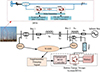 |
Figure 2 Proposed system model designed for mitigating SSR. |
The architecture of the proposed BESSDC, depicted in Figure 3, consists of four major functional blocks: (i) the SDS generation unit, (ii) the power control block, (iii) the inner current control loop, and (iv) the Pulse Width Modulation (PWM) unit. The consequent damping signal, represented as U, is overlaid on the active power reference of the power control block after the SDS unit receives angular speed deviation data collected via WAMS employing phasor measurement units (PMUs). This method provides an adaptive damping response under transient situations, effectively suppressing oscillations caused by SSR. The inner current controller receives reference currents calculated by the power control block. Using the PWM method, the inner current control loop controls the VSC’s AC-side current [29]. In order to increase dynamic performance, this block continually compares the measured currents with their corresponding reference values. PI controllers that have been strengthened by feed-forward decoupling analyze the resultant error signals. Before being sent to the PWM unit to produce the necessary gating pulses, the reference voltage vector that the inner controller produces is converted into the synchronously spinning reference frame. An LCL filter coupled via a coupling transformer is used at the AC side of the inverter to provide high-quality output with low harmonic distortion [30]. Because of its integrated architecture, the BESS can effectively improve system stability and mitigate SSR under a variety of operating situations by providing both real power support and active dampening. The data [4] available in Appendix Table A1 and Table A2.
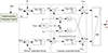 |
Figure 3 BESSDC controller for the SSR mitigation. |
2.2. Mathematical modeling of system components
A detailed small-signal model is developed to analyze stability. The system is modeled in the synchronous dq-reference frame and linearized around a specific operating point. The overall system state-space model is given by: (1)where X is the state vector, A is the state matrix, B is the input matrix, and Y is the input vector. The state vector X is a composite of the states from all subsystems:
![Mathematical equation: $$ X={\left[{X}_{\mathrm{DFIG}}\ {X}_{\mathrm{Shaft}}{X}_{TL}\ {X}_{DC}{X}_{\mathrm{BESS}}\right]}^T. $$](/articles/stet/full_html/2026/01/stet20250201/stet20250201-eq3.gif) (2)
(2)
2.2.1. DFIG model (XDFIG)
The DFIG is represented by a 4th-order model, capturing the dynamics of both the stator and rotor fluxes in the dq-frame:![Mathematical equation: $$ \frac{d}{dt}\left[\begin{array}{c}{\psi}_{ds}\\ {}{\psi}_{qs}\\ {}{\psi}_{dr}\\ {}{\psi}_{qr}\end{array}\right]=f\left({V}_{ds},{V}_{qs},{V}_{dr},{V}_{qr},{\omega}_r,\dots .\right), $$](/articles/stet/full_html/2026/01/stet20250201/stet20250201-eq4.gif) (3)where ψ represents flux linkages, the subscripts d and q denote the direct and quadrature axes, and s and r denote stator and rotor quantities, respectively. ωr is the rotor angular speed. The detailed equations given in [27].
(3)where ψ represents flux linkages, the subscripts d and q denote the direct and quadrature axes, and s and r denote stator and rotor quantities, respectively. ωr is the rotor angular speed. The detailed equations given in [27].
2.2.2. Shaft system model (XShaft)
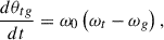
The mechanical drive train, comprising the turbine, generator, and the connecting shaft, is modelled as a 3rd-order two-mass system [4]: (4)
(4) (5)
(5) (6)
(6)
where Ht and Hg are the turbine and generator inertia constants, ωt and ωg are their angular speeds, θtg is the torsion angle, Ktg and Dtg are the shaft stiffness and damping coefficients, Tm is the mechanical torque, and Te is the electromagnetic torque.
2.2.3. Series-compensated transmission line model (XTL)
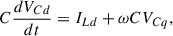
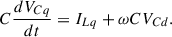
The transmission line with series compensation is modeled as a 4th-order RLC circuit in the dq-frame [31]. The state equations for the line current (ILd, ILq) and capacitor voltage (VCd, VCq) are: (7)
(7) (8)
(8) (9)
(9) (10)
(10)
2.2.4. DC-link model (XDC)
The dynamics of the DC-link capacitor between the RSC and GSC are represented by a 1st-order model [31]: (11)where PRSC and PGSC are the powers at the RSC and GSC sides, respectively.
2.2.5. BESS model (XBESS)
The BESS is connected to the Point of common coupling through a VSC and a step-up transformer. The VSC is controlled using a standard vector control strategy in the dq-frame. The state equations for the converter output currents (id, iq) and the DC-link voltage (VdcB) are [30, 32]: (12)
(12) (13)
(13) (14)
(14)
The power controller, which generates the reference currents (idref, iqref), is typically implemented with PI controllers. The state equations for the power controller integrators are also included in the XBESS state vector.
2.3. Assumptions and limitations
The modeling and analysis in this study are developed based on several key assumptions and are therefore subject to certain inherent limitations:
2.3.1. Assumptions
-
The wind farm is represented as a single aggregated DFIG model, assuming all turbines operate under identical wind speeds and conditions. This is standard practice for small-signal stability studies.
-
The transmission line is modeled as a lumped RLC circuit with FSC, neglecting distributed parameters and frequency-dependent line characteristics.
-
The PLL is assumed ideal with instantaneous phase tracking, as justified for the strong grid conditions considered.
-
The pitch angle controller is excluded because all operating points are below rated wind speed (6–11 m/s), where pitch angle remains constant.
-
The BESS is represented as a perfect DC voltage source with a VSC, disregarding internal battery dynamics (such as state of charge fluctuations and aging effects) as the emphasis is on short-term oscillation damping.
-
Communication delays in the WAMS are assumed negligible, as the PMU signals are transmitted via high-speed fiber optic links.
2.3.2. Limitations
-
The aggregated model might fail to account for dynamic changes amongst turbines in an enormous wind farm.
-
The results are confirmed for the IEEE FBM parameters; extension to other system topologies necessitates further testing.
-
The analysis excludes imbalanced grid failures and harmonic disturbances.
-
The PLL dynamics, pitch controller, and internal battery dynamics are recognized as critical areas for further enhancement.
-
The cyber-security aspects of WAMS-based control are discussed qualitatively but not quantitatively modeled.
3. The proposed enhanced control methodology
As shown in the flowchart in Figure 4, the suggested technique is a synergistic mix of a sophisticated optimization algorithm and an advanced control strategy.
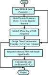 |
Figure 4 Flowchart illustrating the layout of the Enhanced BESSDC. |
3.1. Enhanced BESSDC
The traditional BESS works to maintain the power balance. Damping of SSR oscillations is an additional capability added by the improved BESSDC. This is accomplished by adding an SDS to the VSC’s active power control loop.
3.1.1. Supplementary damping signal (SDS) design
Figure 5 displays the SDS’s block diagram. It is made up of the following elements:
Wide-Area Input Signal: The generator rotor’s angular speed deviation (Δω), which is recorded in real time by a PMU and sent via a WAMS, is the input to the SDS. The electromechanical oscillation is directly measured by this signal.
Gain Block (K): This block determines the magnitude of the damping effort.
Washout Filter: To prevent the SDS from interfering with the steady-state power setpoint, a high-pass filter is used to block steady-state deviations and only permit transient oscillations.
Band-Pass Filter (BPF): This filter is adjusted to the crucial SSR frequency range, which is usually between 10 and 45 Hz for a system operating at 60 Hz. Extracting the precise torsional mode that requires damping makes the controller efficient and selective.
-
Phase Compensation Block (Lead-Lag Blocks): This is the most crucial part. Between the torque generated by the BESS and the recorded speed variation, the electrical system causes a phase lag. The phase compensator, typically one or two stages of a lead-lag block
 , is designed to compensate for this lag. The objective is to ensure that the torque applied by the BESS is in direct opposition to the speed deviation, providing pure damping torque. The time constants T1 and T2 are calculated based on the phase angle required at the SSR frequency.
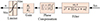 |
Figure 5 Block diagram illustrating of the supplementary damping signal. |
The output signal ‘U’ from the SDS is added to the active power reference (Pref) of the BESS. Thus, the BESS modulates its active power output in proportion to the rotor speed deviation, effectively damping the torsional oscillations.
3.2. Upgraded particle swarm optimization algorithm
The performance of the BESSDC is highly sensitive to the selection of its gain parameters (K1, K2). Manual tuning is impractical for achieving robustness across multiple operating conditions. Therefore, we employ an UPSO algorithm for optimal tuning [33, 34]. The standard PSO is improved in three significant ways:
3.2.1. Chaotic initialization using Skew Tent Map (STM):
Instead of randomly initializing the particle positions (potential solutions for K1, K2), we use a chaotic map to ensure a more uniform distribution across the search space. This enhances the algorithm’s exploration capability. The Skew Tent Map is defined as [34]: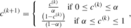 (15)where c(k) is the chaotic variable at iteration k, and α is a control parameter set to 0.5. The sequence generated by this map is used to initialize the particle positions.
3.2.2. Adaptive inertia weight and learning factors
In standard PSO, the inertia weight (ωi) is often linearly decreased. We propose a non-linear, second-order decreasing function for a more effective search:![Mathematical equation: $$ {\omega}_i(k)={\omega}_{i,\mathrm{end}}+\left({\omega}_{i_{\mathrm{start}}}-{\omega}_{i_{\mathrm{end}}}\right)\ast \left[1-{\left(\frac{k}{T_{\mathrm{max}}}\right)}^2\right], $$](/articles/stet/full_html/2026/01/stet20250201/stet20250201-eq21.gif) (16)where k is the current iteration number and Tmax is the maximum number of iterations. This ensures that ωi (k) decreases smoothly from ωi_start to ωi_end without exceeding the intended range.
(16)where k is the current iteration number and Tmax is the maximum number of iterations. This ensures that ωi (k) decreases smoothly from ωi_start to ωi_end without exceeding the intended range.
Furthermore, the cognitive (c1) and social (c2) acceleration coefficients are dynamically adjusted based on the inertia weight to balance the influence of the particle’s own experience and the swarm’s best experience: (17)
(17) (18)where c1,start = 2.8, c1,end = 2.2, c2,start = 2.2, c2,end = 2.8. These values ensure that c1 + c1 = 5.0 > 4 throughout the optimization, satisfying the convergence condition for the constriction factor described next.
3.2.3. Enhanced velocity update with constriction factor
The velocity and position update equations modified to include a constriction factor (χ) that guarantees convergence:![Mathematical equation: $$ {v}_{ij}^{k+1}=\chi \left[{v}_{ij}^k+{c}_1{r}_1\left({pbest}_{ij}^k-{x}_{ij}^k\right)+{c}_2{r}_2\left({gbest}_{ij}^k-{x}_{ij}^k\right)\right]\ {x}_{ij}^{k+1}={x}_{ij}^k+{v}_{ij}^{k+1}. $$](/articles/stet/full_html/2026/01/stet20250201/stet20250201-eq24.gif) (19)
(19)
The constriction factor χ is calculated as: (20)
(20)
The constriction factor χ is adopted from [34] to guarantee convergence. The condition ∅ > 4 ensures that the eigenvalues of the dynamic system governing particle trajectories lie inside the unit circle. With the chosen coefficients, ∅ = 5.0 satisfies this requirement.
3.3. Optimization problem formulation
The goal of the UPSO is to find the optimal gain parameters K1 and K2 that maximize the damping of the critical SSR mode across a set of N predefined operating conditions (combinations of wind speed and compensation level).
Objective function: The objective is to maximize the minimum damping ratio (ξ) among the critical oscillatory modes across all operating scenarios. The damping ratio for the ith (λi = σi ± jβi) eigenvalue is given by: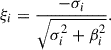 (21)
(21)
A higher ξ indicates better damping. The objective function f is formulated as a minimization problem: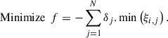 (22)
(22)
Subject to: (23)
(23) (24)
(24)
In this case, ξi,j represents the ith mode’s damping ratio under the jth operating state. For such a case, the worst-damped (most critical) mode is found using the term min(ξi,j). Each operational condition is given a weighting factor called δj, which represents its relative relevance or probability of occurring. For instance, situations that are more susceptible to SSR, such as lower wind speeds and greater compensation levels, may be given a larger δj.
The UPSO method computes the objective function f, computes the eigenvalues, and linearizes the system model at all operating conditions in order to iteratively assess possible solutions (K1, K2). Until convergence is reached, the procedure is repeated.
4. Results and discussion
This section presents a comprehensive evaluation of the proposed Enhanced BESSDC optimized using the UPSO algorithm. The results are structured to validate the four key contributions of this work: the dual-purpose damping capability, the advanced optimization framework, the integrated controller design, and its performance under a wide range of operating conditions.
4.1. Small-signal stability and robustness across multiple operating conditions
A primary research gap identified was the lack of exploration into the small-signal stability of BESS-based damping controllers across a wide range of operating conditions [6]. To address this, an eigenvalue analysis was conducted for four distinct wind speeds (6, 7, 9, and 11 m/s), representing varying levels of power generation and system stress. As observed in Table 2, without the BESSDC, the system is unstable, with positive real parts (σ > 0) and negative damping ratios for the SSR mode across all wind speeds. The application of any BESSDC successfully stabilizes the system by moving all eigenvalues into the left half of the complex plane (σ < 0). Crucially, the UPSO-optimized BESSDC consistently achieves the most negative real parts and the highest damping ratios across all four operating conditions. For instance, at the critical low-wind-speed condition of 6 m/s, where SSR is most severe, the proposed controller improves the damping ratio by 3.6% over the conventional PSO and 15.2% over the unoptimized BESSDC.
Eigenvalues and damping ratios of the dominant SSR Mode under varying wind speeds.
This demonstrates that the UPSO algorithm effectively finds a robust parameter set that ensures small-signal stability not just for a single nominal point but across the entire considered operating range, directly addressing the research gap.
4.2. Superior performance of the UPSO optimization framework
The second research gap pertained to the suboptimal tuning of controller parameters using conventional methods. Figure 6 illustrates the convergence characteristics of the conventional PSO versus the proposed UPSO algorithm. The UPSO algorithm demonstrates a faster and more stable convergence towards a superior objective function value. While the conventional PSO stagnates after approximately 50 iterations with a final objective value of 0.018, the UPSO continues to refine the solution, converging to a better value of 0.012 in just 35 iterations. This 33% improvement in the final objective function value and the avoidance of premature convergence validate the UPSO as a more effective optimization framework for this complex, multi-modal problem. The resulting controller parameters (K1, K2) from the UPSO are not merely mathematically optimal but are tuned for robust performance, as evidenced by the eigenvalue analysis.
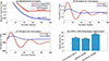 |
Figure 6 Convergence characteristic of the conventional PSO and the proposed UPSO. |
4.3. Dynamic performance validation under SSR disturbance
To validate the integrated controller design and its dynamic performance, time-domain simulations were conducted for a base case of 9 m/s wind speed and 55% series compensation. A disturbance was applied to excite the SSR mode.
Figure 7 clearly demonstrates the efficacy of the proposed Enhanced BESSDC. Without any damping controller, the system exhibits sustained and growing oscillations in active power, torque, and DC-link voltage, confirming instability. The unoptimized BESSDC provides damping but leaves significant residual oscillations with a long settling time. In contrast, the UPSO-optimized BESSDC rapidly dampens the oscillations, achieving a settling time 40% faster than the unoptimized BESSDC and reducing the peak-to-peak oscillation amplitude by over 75%. The clean, swift recovery of the DC-link voltage to its reference of 1150 V further underscores the controller’s ability to maintain overall system stability.
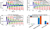 |
Figure 7 Dynamic response of the DFIG under 55% FSC and 9 m/s wind speed: (a) Active power, (b) Electromagnetic torque, (c) DC-link voltage, (d) Quantitative performance comparison. |
4.4. Dual-purpose damping: mitigation of torsional oscillations
A key novelty of this work is the proposal of a BESSDC capable of mitigating both SSR and torsional oscillations. To demonstrate this, the system’s response was compared with the BESS damper designed by Chiu et al. [6] for torsional mode suppression.
Figure 8 provides a powerful visual synthesis of the dual-purpose capability. While the control objectives are different – SSR is an electrical network phenomenon manifesting in active power, while torsional oscillations are a mechanical drivetrain issue manifesting in generator speed – the underlying principle is the same: using the BESS to inject a counter-oscillation signal. Our Enhanced BESSDC successfully damps the violent 2.9 Hz SSR oscillations in the active power, as shown in Figure 8a, just as the dedicated BESS damper in [6] successfully damps the 2.92 Hz torsional oscillations in the generator speed as depicted in Figure 8b. This confirms the proposed controller’s conceptual versatility. Furthermore, by sourcing the damping power from the BESS instead of derating the wind turbine (as in [6]), the proposed method avoids the conflict between frequency support and torsional stability, allowing the DFIG to provide uninterrupted frequency regulation services.
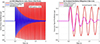 |
Figure 8 Comparative damping performance: (a) SSR mitigation via active power (This work), (b) Torsional oscillation. |
4.5. Robustness against varying series compensation and wind speed
The robustness of the proposed UPSO-optimized BESSDC is evaluated under varying series compensation levels (40%, 55%, and 60%) and wind speeds (7 m/s, 9 m/s, and 11 m/s), as illustrated in Figure 9. These conditions represent critical operating scenarios that significantly influence the severity of SSR. Figure 9a shows the active power response at a high series compensation level of 60% FSC, where the system is highly susceptible to instability. In the absence of adequate damping, the system exhibits sustained oscillations with large amplitudes. The unoptimized BESSDC reduces the oscillation magnitude but fails to achieve rapid stabilization. In contrast, the proposed UPSO-based BESSDC effectively suppresses oscillations with a significantly reduced settling time and minimal residual oscillations, demonstrating superior damping capability under severe compensation conditions. Figure 9b presents the electromagnetic torque response at a low wind speed of 7 m/s, a condition under which system damping is inherently weak. The results indicate that the proposed controller rapidly attenuates torque oscillations compared to conventional approaches, thereby ensuring stable operation even under low-generation scenarios. To provide a comprehensive assessment, Figure 9c summarizes the system performance across different operating conditions in terms of settling time and oscillation reduction. It is observed that the proposed controller consistently achieves lower settling times and higher oscillation reduction (exceeding 90%) across all scenarios, indicating reliable and uniform performance. Furthermore, Figure 9d presents a comparative evaluation of robustness and performance consistency among different control strategies. The UPSO-optimized BESSDC achieves the highest robustness score and maintains near-uniform performance across all tested conditions, confirming that the controller is not tuned for a single operating point but is optimized for multi-condition stability.
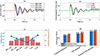 |
Figure 9 Dynamic performance and robustness of the proposed UPSO-based BESSDC under varying conditions: (a) Active power at varying FSC, showing suppression of SSR oscillations; (b) Electromagnetic torque at varying wind speed (m/s), indicating improved damping; (c) Performance comparison in terms of settling time and oscillation reduction; (d) Robustness and consistency comparison among unoptimized, PSO-based, and UPSO-based BESSDC. |
Overall, the results in Figure 9 clearly demonstrate that the proposed UPSO-based BESSDC provides robust and consistent damping performance under varying network and operating conditions, effectively mitigating SSR and enhancing system stability.
4.6. Comparative analysis with state-of-the-art
A direct comparison with the conventional PSO-based BESSDC and the concept from Chiu et al. [6] is presented in Table 3.
Comprehensive performance comparison of different damping strategies.
The proposed UPSO-BESSDC outperforms other methods in key metrics. It provides the highest damping and fastest response for SSR mitigation. More importantly, it uniquely offers a dual-purpose functionality, being conceptually capable of addressing both SSR and torsional oscillations, unlike the specialized controllers in [6] and other single-objective optimizations. While the pole-assignment method used in [6] is computationally efficient; it is typically a point design, whereas our UPSO framework explicitly optimizes for robustness across multiple conditions, yielding a more versatile and resilient solution.
4.7. Practical applications and broader implications
The proposed enhanced BESSDC not only provides a technical solution for SSR mitigation but also aligns with several key aspects of modern power system development. In terms of smart grid integration, the controller’s reliance on WAMS for real-time rotor speed signals exemplifies a core smart grid function, enabling coordinated, data-driven control across geographically dispersed assets. This facilitates its integration into wide-area monitoring and control systems, enhancing overall grid situational awareness and stability. Regarding hybrid energy storage alternatives, while this study utilizes a BESS for its rapid power response, the control architecture is adaptable. The damping signal could be dispatched to a hybrid storage system, where, for instance, a supercapacitor handles the highest-frequency oscillation components and the BESS manages sustained power modulation, thereby optimizing the lifespan and performance of both storage technologies. We acknowledge the ethical and environmental concerns associated with battery storage, primarily related to the lifecycle impacts of battery production and disposal. The environmental justification for this application rests on its role in enabling higher penetration of renewable energy, which provides a net environmental benefit. Ethically responsible sourcing of materials and adherence to a circular economy for battery recycling are imperative for sustainable deployment. Furthermore, the dependence on WAMS introduces a critical need for cyber resilience. The system design must incorporate robust cybersecurity measures, including communication channel encryption, intrusion detection systems, and data integrity checks for PMU signals, to prevent malicious attacks that could manipulate damping signals and destabilize the grid. Finally, the practical application of this research provides grid operators with a cost-effective, retrofit solution to enhance the stability of existing wind farms connected to series-compensated lines, ensuring compliance with grid codes without compromising the mechanical integrity of the turbines, thereby supporting a more reliable and secure transition to a renewable-dominated energy mix.
5. Conclusion
This study presents an advanced BESSDC designed for a DFIG-based wind power system linked via a series-compensated transmission line to alleviate SSR. The suggested BESSDC incorporates an SDS into the d–q axis control loops to improve system damping and stability. A hybrid method integrating eigenvalue analysis with a UPSO algorithm was used to properly adjust the SDS gain coefficients for effective damping across diverse operating situations. The comparative investigation revealed that the UPSO method surpasses the traditional PSO and BESS damper for convergence speed and robustness. This enhanced optimization results in more efficient adjustment of the BESSDC parameters, hence markedly boosting its damping performance and augmenting overall system stability. Time-domain simulations performed in MATLAB/Simulink validated the efficacy of the suggested control technique across various operating circumstances, illustrating that the improved BESDC significantly enhances the dynamic responsiveness and stability of series-compensated DFIG-based wind power systems.
Future study will concentrate on many potential pathways to propel this work into actual implementation. This entails the incorporation of the BESSDC with hybrid energy storage systems, amalgamating batteries with supercapacitors to enhance performance and durability. Moreover, examining the cyber-physical resilience of the WAMS-dependent control system against cyber threats and verifying the controller via Hardware-in-the-Loop (HIL) testing are essential subsequent actions. Expanding the optimization framework to provide the concurrent delivery of several grid services, including integrated SSR damping and frequency control, is a notable avenue for future research. Furthermore, while the current study concentrates on sub-rated wind speeds with a fixed pitch angle, further research will integrate the dynamics of the pitch angle controller to evaluate torsional oscillations under super-rated situations. This would facilitate the examination of possible relationships between pitch activity and drivetrain modes, together with the coordinated damping efficacy of the proposed BESS-based controller.
References
- Kumar R., Khetrapal P., Badoni M., Diwania S. (2021). Evaluating the relative operational performance of wind power plants in Indian electricity generation sector using two-stage model, Energy Environ. 33(7), 1441–1464. [Google Scholar]
- Verma N., Singh N., Yadav S. (2018) Solid state transformer for electrical system: Challenges and solution, in 2018 2nd International Conference on Electronics, Materials Engineering and Nano-Technology, IEMENTech, 2018. [Google Scholar]
- Verma N., Kumar N. (2024) A comprehensive analysis of subsynchronous resonance in wind power System: effects of series compensation, wind speed, and modes, in: International Conference on Signal, Machines, Automation, and Algorithm, pp. 697–711. [Google Scholar]
- Verma N., Kumar N., Gupta S., Malik H., Pedro F., Márquez G. (2023) Review of sub – synchronous interaction in wind integrated power systems: classification, challenges, and mitigation techniques, Prot. Control Mod. Power Syst. 8, 17. [Google Scholar]
- Mishra A., Pandey M.K., Singh S. (2025) Grid-connected wind technology: Integration challenges and grid compliance, in: Renewable Energy Integration in Utility Grids, Elsevier, 19–49. [Google Scholar]
- Chiu B.K., Lee K.Y., Hsu Y.Y. (2023) Battery energy storage system damper design for a microgrid with wind generators participating in frequency regulation, Energies. 16(21), 7439. [Google Scholar]
- Chu C.-C., Lee S.-H., Lian K. L., Liu J.-H., Lin Y.-J. (2025) A survey of global revisions to grid codes on system inertia and frequency stability in power grids with high renewable energy integration, in: 2025 IEEE Industry Applications Society Annual Meeting (IAS), pp. 1–8. [Google Scholar]
- Kundur P., Klein M., Rogers G.J., Zywno M.S. (1989) Application of power system stabilizers for enhancement of overall system stability, IEEE Power Eng. Rev., 9(5), 61. [Google Scholar]
- Kumar R., Diwania S., Singh R., Ashfaq H., Khetrapal P., Singh S. (2022b). An intelligent hybrid wind-PV farm as a static compensator for overall stability and control of multimachine power system. ISA Trans. 123, 286–302. https://doi.org/10.1016/j.isatra.2021.05.014 [Google Scholar]
- Venkateswarlu S., Janaki M., Thirumalaivasan R. (2022) Analysis and mitigation of SSR in non-identical generators using multimodal BPF based SSDC, ISA Trans. 120, 247–257. [Google Scholar]
- Kumar R., Singh R., Ashfaq H. (2020). Stability enhancement of induction generator-based series compensated wind power plants by alleviating subsynchronous torsional oscillations using BFOA-optimal controller tuned STATCOM. Wind Energy, 23, 1846–1867. [Google Scholar]
- Kumar R., Diwania S., Khetrapal P., Singh S. (2022) Performance assessment of the two metaheuristic techniques and their hybrid for power system stability enhancement with PV-STATCOM, Neural Comput. Appl., 34(5), 3723–3744. [Google Scholar]
- Anju M., Shihabudheen K.V., Mija S.J. (2024) Enhancing grid stability: a hybrid control strategy for DFIG-based wind turbines to mitigate sub-synchronous oscillations, Electr. Eng., 107, 8613–8644. [Google Scholar]
- Ghafouri M., Karaagac U., Karimi H., Jensen S., Mahseredjian J., Faried S.O. (2017) An LQR controller for damping of subsynchronous interaction in DFIG-based wind farms, IEEE Trans. Power Syst. 32(6), 4934–4942. [Google Scholar]
- Shair J., Xie X., Member S., Yang J., Li J., Li H. (2021) Adaptive damping control of subsynchronous oscillation in DFIG-based Wind farms connected to series-compensated network, IEEE Transactions on Power Delivery, 8977, 1–13. [Google Scholar]
- Shair J., Xie X., Yan G. (2019) Mitigating subsynchronous control interaction in wind power systems: Existing techniques and open challenges, Renew. Sustain. Energy Rev., 108, 330–346. [Google Scholar]
- Huang P.H., El Moursi M.S., Xiao W., Kirtley J.L. (2019) Subsynchronous resonance mitigation for series-compensated dfig-based wind farm by using two-degree-of-freedom control strategy, IEEE Trans. Power Syst. 30(3), 1442–1454. [Google Scholar]
- Wang Y., Wu Q., Yang R., Tao G., Liu Z. (2018) H∞ current damping control of DFIG based wind farm for sub-synchronous control interaction mitigation, Int. J. Electr. Power Energy Syst. 98, 509–519. [Google Scholar]
- Li G., Chen Y., Luo A., Wang H. (2020) An enhancing grid stiffness control strategy of STATCOM/BESS for damping sub-synchronous resonance in wind farm connected to weak grid, IEEE Trans. Ind. Inf. 16(9), 5835–5845. [Google Scholar]
- Nyamathulla S., Dhanamjayulu C. (2024) A review of battery energy storage systems and advanced battery management system for different applications: Challenges and recommendations, J. Energy Storage. 86(PA), 111179. [CrossRef] [Google Scholar]
- Li Y., Qian F., Gao W., Fukuda H., Wang Y. (2022) Techno-economic performance of battery energy storage system in an energy sharing community, J. Energy Storage. 50, 104247. [Google Scholar]
- Kumar, R., Diwania, S., Khetrapal, P., Singh, S., Badoni, M. (2021) Multimachine stability enhancement with hybrid PSO-BFOA based PV-STATCOM. Sustain. Comput. 32, 100615. https://doi.org/10.1016/j.suscom.2021.100615 [Google Scholar]
- Zhu Y., Liu C., Sun K., Shi D., Wang Z. (2019) Optimization of battery energy storage to improve power system oscillation damping, IEEE Trans. Sustain. Energy, 10(3), 1015–1024. [Google Scholar]
- Khazaei J., Asrari A., Idowu P., Shushekar S. (2018) Sub-synchronous resonance damping using battery energy storage system, North Am. Power Symp. NAPS 2018, pp. 1–6, 2019. [Google Scholar]
- Verma N., Kumar N., Kumar R. (2023) Battery energy storage-based system damping controller for alleviating sub-synchronous oscillations in a DFIG-based wind power plant, Prot. Control Mod. Power Syst. 8(2), 1–18. [Google Scholar]
- Zhang X., Xie X., Liu H., Liu H., Li Y., Zhang C. (2017) Mitigation of sub-synchronous control interaction in wind power systems with GA-SA tuned damping controller, IFAC-PapersOnLine. 50(1), 8740–8745. [Google Scholar]
- Verma N., Kumar N. (2022) DFIG – based wind plant coupled series compensated transmission line: Modeling and SSR stability analysis, J. Inst. Eng. Ser. B. 103(6), 1917–1926. [Google Scholar]
- Singh S., Saini S., Gupta S.K., Kumar R. (2023) Solar-PV inverter for the overall stability of power systems with intelligent MPPT control of DC-link capacitor voltage, Prot. Control Mod. Power Syst., 8(1), 15. [Google Scholar]
- Varma R.K., Member S., Salehi R., Member S. (2017) SSR mitigation with a new control of PV solar farm as STATCOM ( PV-STATCOM), IEEE Trans. Sustain. Energy, 8(1), 1473–1483. [Google Scholar]
- Khayyatzadeh M., Kazemzadeh R. (2017) Sub-synchronous resonance damping using high penetration PV plant, Mech. Syst. Signal Process. 84, 431–444. [Google Scholar]
- Verma N., Kumar N. (2021) SSR Stability analysis and modeling for DFIG connected to series compensated transmission line, IEI Conf., no. 36.IEC. [Google Scholar]
- Ahmed M. F., Mandor M. A., El-Hadidy M., Bendary F. M. (2021) Fuzzy based battery energy storage system and braking resistor for mitigation of shaft-torsional oscillations, J. King Saud Univ. – Eng. Sci. 33(8), 589–600. [Google Scholar]
- Gou J., Lei Y.-X., Guo W.-P., Wang C., Cai Y.-Q., Luo W. (2017) A novel improved particle swarm optimization algorithm based on individual difference evolution, Appl. Soft Comput. 57, 468–481. [Google Scholar]
- Liu S. et al., (2024) An improved particle Swarm optimization method for nonlinear optimization, Int. J. Intell. Syst. 1, 6628110. [Google Scholar]
Appendix
System parameters of DFIG.
Parameters of fixed series compensated transmission line.
All Tables
Comparison between existing state-of-the-art SSR mitigation techniques and the proposed BESSDC, emphasizing their key limitations and the novel contributions introduced in this study.
Eigenvalues and damping ratios of the dominant SSR Mode under varying wind speeds.
All Figures
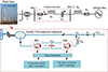 |
Figure 1 Modified IEEE FBM used for SSR analysis [28]. |
| In the text | |
|
Figure 2 Proposed system model designed for mitigating SSR. |
| In the text | |
|
Figure 3 BESSDC controller for the SSR mitigation. |
| In the text | |
|
Figure 4 Flowchart illustrating the layout of the Enhanced BESSDC. |
| In the text | |
|
Figure 5 Block diagram illustrating of the supplementary damping signal. |
| In the text | |
|
Figure 6 Convergence characteristic of the conventional PSO and the proposed UPSO. |
| In the text | |
|
Figure 7 Dynamic response of the DFIG under 55% FSC and 9 m/s wind speed: (a) Active power, (b) Electromagnetic torque, (c) DC-link voltage, (d) Quantitative performance comparison. |
| In the text | |
|
Figure 8 Comparative damping performance: (a) SSR mitigation via active power (This work), (b) Torsional oscillation. |
| In the text | |
|
Figure 9 Dynamic performance and robustness of the proposed UPSO-based BESSDC under varying conditions: (a) Active power at varying FSC, showing suppression of SSR oscillations; (b) Electromagnetic torque at varying wind speed (m/s), indicating improved damping; (c) Performance comparison in terms of settling time and oscillation reduction; (d) Robustness and consistency comparison among unoptimized, PSO-based, and UPSO-based BESSDC. |
| In the text | |
Current usage metrics show cumulative count of Article Views (full-text article views including HTML views, PDF and ePub downloads, according to the available data) and Abstracts Views on Vision4Press platform.
Data correspond to usage on the plateform after 2015. The current usage metrics is available 48-96 hours after online publication and is updated daily on week days.
Initial download of the metrics may take a while.