")
")
| Issue |
Sci. Tech. Energ. Transition
Volume 80, 2025
Emerging Advances in Hybrid Renewable Energy Systems and Integration
|
|
|---|---|---|
| Article Number | 16 | |
| Number of page(s) | 6 | |
| DOI | https://doi.org/10.2516/stet/2024095 | |
| Published online | 27 January 2025 | |
Regular Article
A novel hydrogen production system based on multistage reverse electrodialysis
Department of Energy and Power Engineering, Shanxi Institute of Energy, No. 63, University Street, Yuci District, Jinzhong 030600, Shanxi, P.R. China
* Corresponding author: This email address is being protected from spambots. You need JavaScript enabled to view it.
Received:
30
August
2024
Accepted:
21
October
2024
Abstract
Salinity gradient energy can be converted into hydrogen energy through the system combining Multi-Stage Reverse ElectroDialysis (MSRED) with polymer electrolyte membrane water electrolysis. However, the relevant performance of the system has never been investigated. In this paper, the influence of relevant parameters of MSRED on the performance of the system was analyzed theoretically through a reliable mathematical model. The results showed that increasing the flow velocity of solutions will cause a remarkable decrease in the energy recovery of the system, although the total output power and Hydrogen Production Rate (HPR) of the system increases correspondingly. Besides, thickening compartments of the high-concentration solution are effective in reducing the energy consumption for pump with a small augment in the total output power and HPR of the system, while the energy recovery of the system is still dropping slowly.
Key words: Salinity gradient energy / Multi-stage reverse electrodialysis / Polymer electrolyte membrane / Water electrolysis
© The Author(s), published by EDP Sciences, 2025
 This is an Open Access article distributed under the terms of the Creative Commons Attribution License (https://creativecommons.org/licenses/by/4.0), which permits unrestricted use, distribution, and reproduction in any medium, provided the original work is properly cited.
1 Introduction
Hydrogen is a clean and efficient energy which has the potential to play an important role in the future energy structure. The technology of hydrogen production through hydrolysis is becoming increasingly important [1]. According to the global annual river flow, the energy of salt difference exceeds 1.4 TW [2, 3]. Furthermore, the huge amount of Low-Grade Heat (LGH), especially with a temperature below 100 ℃, can be converted into SGE through thermal separation, which enhances the potential of this energy. Recently, a novel technology named Reverse ElectroDialysis Heat Engine (REDHE) which can convert LGH into electricity, has been getting more and more attention in the world [4–11]. The thermal separation process within the REDHE unit differentiates the mixed salt solution into High-Concentration (HC) and Low-Concentration (LC) streams using LGH. This accomplishment of the “heat to SGE” conversion occurs here. Subsequently, both streams are directed into the Reverse ElectroDialysis (RED) unit where the SGE is harnessed to produce electricity, i.e., the so-called “SGE to power” process. The working principle of RED whose principle can be observed in Figure 1 is to generate electrical energy through the flow of salt solutions of different concentrations in HC and LC solution chambers formed by alternately stacking Cation Exchange Membranes (CEMs) and Anion Exchange Membranes (AEMs). The core technology of REDHE is RED. Figure 1 illustrates the selectivity of ion exchange membranes (IEMs), positive ions and negative ions in HC solution can only migrate in one direction and the opposite direction respectively. Therefore, once the oxidation-reduction reaction on the electrode begins, the ion current in the RED stack is converted and eventually converted into electrical energy [12]. Nowadays, there are main two methods to produce hydrogen by RED. One method is producing hydrogen within the cathode chamber of RED stacks directly. And some researchers have implemented the relevant studies [13–16]. However, this method seems unpractical since increasing the number of RED cells can not elevate the current density although the overpotential needed by electrode reaction has been achieved [3]. The other one is combining RED with an independent water electrolysis plant, like the Polymer Electrolyte Membrane (PEM) water electrolysis. R.A. Tufa et al. [1] investigated a RED and PEM hydrogen production system with a 27-cell-pairs RED stack. The results indicated that the maximum Hydrogen Production Rate (HPR) of the system could reach 44 cm3 · h−1 per cm2 of electrode surface area at 65 ℃, when the output voltage and current of the RED stack were 1.8 V and 0.48 A, respectively.
 |
Fig. 1 Schematic representation of reverse electrodialysis process. |
In order to harvest more SGE from salt solutions, Multi-Stage RED (MSRED) in series control is superior to the single RED stack [17]. Therefore, in this paper, the hybrid MSRED-PEM water electrolysis system was proposed to produce hydrogen. The effect of relevant parameters of MSRED on the performance of the system was analyzed theoretically through a mathematical model which has been verified in reference [17].
2 Mathematical model
2.1 Introduction to the system
Figure 2 shows the principle of the hybrid MSRED-PEM water electrolysis system for hydrogen production. This system mainly consists of three components, i.e., MSRED stacks, the DC-DC converter, and the PEM water electrolyzer. Firstly, HC and LC solutions flow through the MSRED where all of the RED stacks are controlled in series with an equal current. Then the total output power of the MSRED is reduced its voltage by the DC-DC converter. Finally, the converted power is used to drive the PEM water electrolyzer to generate hydrogen. Compared with the single RED stack, MSRED can harvest more SGE since the phenomenon of electrodialysis occurring in the single RED stack is able to be alleviated or even eliminated in MSRED due to its capacity to adapt to the variation of the electromotive force [17]. In general, the cell voltage of the PEM water electrolyzer should remain below 2.0 V from the material science viewpoint and industrial PEM water electrolyzers usually operate in the 800–1200 A · m−2 [18]. However, the current density of a RED stack is usually not exceeding 50 A · m−2 [17]. Moreover, with RED cells increasing, the output voltage of the stack elevates while the current density remains unchangeable. Therefore, the DC-DC converter is necessary for the system to turn down the output voltage of MSRED, and thus the current provided to the PEM water electrolyzer is increased.
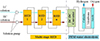 |
Fig. 2 Schematic representation of the integrated MSRED-PEM electrolysis setup for hydrogen generation. |
2.2 Model of the hybrid MSRED-PEM water electrolysis system
For the NaCl solution, the open voltage of a RED stack is the sum of the Nernst potential difference across CEMs and AEMs: (1)where N represents the number of cell pairs, R is the universal gas constant, T is the temperature in Kelvin, and F denotes the Faraday constant. β is the permselectivity correction factor, αCEM and αAEM are the permselectivity of both IEMs, and γ and C are the mean ion activity coefficient of IEMs and the concentration of solutions. The notations HC and LC denote solutions of high and low concentrations, respectively.
According to Ohm’s law, the output voltage of the RED stack can be written as: (2)where I is the current, Rstack is the total internal resistance of the stack, which is the sum of the total cell pairs resistance (Rcells) and the resistance of electrode compartments (Rblank):
 (3)
(3)
It is worth noting that Rblank can be negligible when a high number of cell pairs are equipped in the stack.
The output power of the RED stack can be expressed by: (4)
(4)
For the MSRED controlled in series, currents of all RED stacks are equal, and the output voltage of the MSRED is the sum of that of all RED stacks: (5)where Nstack is the number of RED stacks in the MSRED.
The total output power of the MSRED is defined as: (6)
(6)
The energy input required for solution pumping cannot be neglected. The total pump power of MSRED can be calculated using the following formula [19]: (7)where ΔPHC and ΔPLC are pressure drops of HC and LC solutions through the MSRED respectively, ηpump is the pump efficiency and is set to 75%. QHC and QLC are the volume flow rates, which are [20]:
 (8)
(8)
 (9)where ε is spacer porosity, and b and d are respectively the width and thickness of solution compartments. And v is the flow velocity of solutions.
The HPR of the system is defined as: (10)where Ie is the current provided to the PEM electrolyzer. The conversion efficiency factor, η, is deemed to be 80%. Additionally, z represents the equivalent electrons per mole of hydrogen. [21].
The energy recovery of the system can be written as: (11)where ΔH is the enthalpy of hydrogen with the value of 285.8 kJ · mol−1 when temperature and pressure are respectively 298 K and 1 atm. SGE is the salinity gradient energy between the initial HC and LC solutions, which can be calculated according to the Reference [17].
3 Results and discussion
3.1 Design of the system
Each stack in the MSRED comes with 5000 cells intended for business use. The active dimensions of the IEMs are 1 m × 0.1 m (width × length), and the performance and geometric details of the IEMs are presented in Table 1. The thicknesses of HC and LC compartments are 100 μm. Initial concentrations of HC and LC solutions are respectively 5 M and 0.05 M. Initial value of the flow velocity of the solutions is 1 cm · s−1. In order to make the net total output power of MSRED (Pnet,tot) (i.e., the total output power minus the pump power) maximum, the number of stacks (Nstack) and the current should be optimized. Figure 3 shows the effect of Nstack and the current on Pnet,tot. From Figure 3, it can be seen that the maximum Pnet,tot can be obtained when Nstack and the current are respectively 11 and 4.25 A, which will be adopted in the next investigations. Besides, 10 PEM water electrolyzer cells are adopted in the system, and the voltage of a PEM water electrolyzer cell is usually below 2 V, thus the design voltage of it being set as 1.8 V. The cell resistance of a cell is set as 260 mΩ · cm2 [18].
 |
Fig. 3 The alteration in the total net output power of the MSRED, contingent upon the number of RED stacks and the current flow, under the proposed design specifications. |
3.2 Influence of flow velocity
In this section, the effects of the flow velocity (v) of solutions on the relevant performance of the MSRED-PEM electrolyzer are investigated.
Figure 4 presents variations of the total output power (P) and the pump power (Ppump) with the flow velocity of solutions (v). As shown in Figure 4, with v increases from 0.8 cm · s−1 to 2 cm · s−1, P has a nearly 80% rise compared with its initial value of 11.45 kW, and Ppump increases from 2.04 kW to 13.43 kW nearly 6.6 times. The flow of HC and LC solutions in compartments facilitates the conversion of the SGE between these two solutions into electricity progressively. Thus the concentration difference between the solutions is becoming more and more small. Increasing v means that more SGE is flowing into the MSRED at the same time, thus more SGE being able to be harvested, which indicates the augment of P. However, that is at the cost of more power input for pumping.
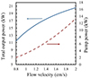 |
Fig. 4 Flow velocity of solutions affects the total output power and the pump power under the design condition. |
Due to P increasing with v, the HPR keeps a similar tendency of variation with v to that of P. As presented in Figure 5, as v equals 0.8 cm · s−1, 108.47 mole hydrogen can be produced per hour, and this value raises to 145.45 when v equals 2 cm · s−1. On the contrary, energy recovery of the system (ηsystem) drops from 20.1 % to 10.0 % with the increasing v. There are two main reasons for the reduction of ηsystem. Firstly, elevating v makes more SGE between the solutions input the MSRED. Dissipation of the SGE caused mainly by the internal resistance of the MSRED and unused SGE leaving from it are both increasing although more output power is being generated [17]. Secondly, energy consumption by the pump also increases. Therefore, according to equation (11), the descent of energy recovery of the system occurs.
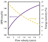 |
Fig. 5 Flow velocity of solutions effects on the HPR and the energy recovery of the system under the design condition. |
As analyzed above, increasing v in excess seems not a wise measure to improve the performance of the MSRED-PEM water electrolyzer, especially when HC and LC solutions are regenerated by LGH.
3.3 Influence of the thickness of HC solution compartments
The previous section indicates that the augment of solution flow velocity triggers severe energy consumption by the pump, although more SGE can be harvested by the MSRED and higher HPR can be achieved for the system correspondingly. In order to enhance the HPR of the system while reducing pump power, thickening HC solution compartments may be a good choice [24]. As illustrated in Figure 6, when the thickness of HC solution compartments (dHC) varies from 100 μm to 300 μm, P increases by 13.2 % up to 15.84 kW. This is because increasing dHC while keeping HC solution flow velocity unchanged makes more HC solution (i.e., more SGE) flow into the MSRED at the same time, while the internal resistance of the MSRED does not increase remarkably due to the high conductivity of the HC solution. Meanwhile, the Ppump drops with the increasing dHC. As shown in Figure 6, a nearly 57.9 % decrease in Ppump can be achieved when dHC increases from 100 μm to 300 μm.
 |
Fig. 6 The thickness of HC solution compartments influences on the total output power and the pump power under the design condition. |
Figure 7 presents the influence of dHC on HPR and energy recovery of the system under the design condition. Since more SGE can be captured by the MSRED when dHC increases, HPR raises with dHC as well. Compared with the influence of v, the effect of dHC on HPR is less remarkable with a mere 6.4 % augment in HPR. For the energy recovery of the system, increasing dHC also makes it drop slowly due to more SGE flowing into the system although energy consumption for pumping decreases.
 |
Fig. 7 The thickness of HC solution compartments influences on HPR and the energy recovery of the system under the design condition. |
4 Conclusions
This study presents an investigation of an MSRED-PEM water electrolysis system intended for hydrogen production, which was examined conceptually. By fine-tuning the number of RED stacks and the MSRED current, the highest possible capture of the SGE between the HC and LC solutions was realized. Subsequently, the impact of flow rate (v) and the difference in concentration (dHC) on the system’s efficacy was analyzed. The findings of the research are as follows:
-
When the number of RED stacks and the current of MSRED are respectively 11 and 4.25 A, the net total output power of the MSRED reaches the peak value of 10.75 kW under the design condition.
-
Increasing v makes P and HPR rise remarkably due to more SGE input into the system, while pump power increases dramatically as well. It results in more than one-fold reduction in ηsystem compared with its initial value of 20.1 % when v equals 0.8 cm · s−1.
-
Increasing dHC while keeping the velocity of HC solution unchanged can reduce pump power with a small enhancement in P and HPR since more SGE flows into the system. However, ηsystem decreases slowly from 17.5 % to 15.3 % when dHC increases from 100 μm to 300 μm.
Funding
The project was supported by Shanxi Province Education Science “14th Five-Year Plan” 2023 annual topic under the Research and practice of heat transfer based on case-based teaching under the background of “carbon dioxide emission and carbon neutrality” (GH-230230); 2023 Shanxi Institute of Energy fund project under the Study on the performance of reverse electrodialysis denitration reactor driven by flue gas waste heat (ZY-2023023).
Conflicts of interest
The author declared no potential conflicts of interest concerning the research, authorship, and/or publication of this article.
Data availability statement
The datasets used and/or analyzed during the current study are available from the corresponding author upon reasonable request.
References
- Tufa R.A., Rugiero E., Chanda D., Hnàt J., van Baak W., Veerman J., Fontananova E., Di Profio G., Drioli E., Bouzek K., Curcio E. (2016) Salinity gradient power-reverse electrodialysis and alkaline polymer electrolyte water electrolysis for hydrogen production. J. Memb. Sci. 514, 155–164. [CrossRef] [Google Scholar]
- Wick G.L., Schmitt W.R. (1977) Prospects for renewable energy from the sea. Mar. Technol. Soc. J. 11, 16–21. [Google Scholar]
- Weinstein J.N., Leitz F.B. (1976) Electric power from differences in salinity: the dialytic battery. Science 191, 557–559. [CrossRef] [PubMed] [Google Scholar]
- Palenzuela P., Micari M., Ortega-delgado B., Giacalone F., Zaragoza G., Alarcón-Padilla D.-C., Cipollina A., Tamburinia A., Micale G.M. (2018) Performance analysis of a RED-MED salinity gradient heat engine. Energies 11, 3385. [CrossRef] [Google Scholar]
- Micari M., Cipollina A., Giacalone F., Kosmadakis G., Papapetrou M., Zaragoza G., Micale G., Tamburini A. (2019) Towards the first proof of the concept of a reverse electrodialysis – membrane distillation heat engine. Desalination 453, 77–88. [CrossRef] [Google Scholar]
- Olkis C., Santori G., Brandani S. (2018) An adsorption reverse electrodialysis system for the generation of electricity from low-grade heat. Appl. Energy 231, 222–234. [CrossRef] [Google Scholar]
- Brogioli D., La Mantia F., Yip N.Y. (2019) Energy efficiency analysis of distillation for thermally regenerative salinity gradient power technologies. Renew. Energy 133, 1034–1045. [CrossRef] [Google Scholar]
- Giacalone F., Olkis C., Santori G., Cipollina A., Brandani S., Micale G. (2019) Novel solutions for closed-loop reverse electrodialysis: thermodynamic characterization and perspective analysis. Energy 166, 674–689. [CrossRef] [Google Scholar]
- Hu J., Xu S., Wu X., Wu D., Jin D., Wang P., Leng Q. (2018) Theoretical simulation and evaluation for the performance of the hybrid multi-effect distillation – reverse electrodialysis power generation system. Desalination 443, 172–183. [CrossRef] [Google Scholar]
- Long R., Li B., Liu Z., Liu W. (2017) Hybrid membrane distillation-reverse electrodialysis electricity generation system to harvest low-grade thermal energy. J. Memb. Sci. 525, 107–115. [CrossRef] [Google Scholar]
- Tamburini A., Tedesco M., Cipollina A., Micale G., Ciofalo M., Papapetrou M., Van Baak W., Piacentino A. (2017) Reverse electrodialysis heat engine for sustainable power production. Appl. Energy. 206, 1334–1353. [CrossRef] [Google Scholar]
- Galama A.H., Vermaas D.A., Veerman J., Saakes M., Rijnaarts H.H.M., Post J.W., Nijmeijer K. (2014) Membrane resistance: the effect of salinity gradients over a cation exchange membrane. J. Memb. Sci. 467, 279–291. [CrossRef] [Google Scholar]
- Watson V.J., Hatzell M., Logan B.E. (2015) Bioresource technology hydrogen production from continuous flow, microbial reverse-electrodialysis electrolysis cells treating fermentation wastewater. Bioresour. Technol. 195, 51–56. [CrossRef] [Google Scholar]
- Song Y., Hidayat S., Kim H., Park J. (2016) Bioresource technology hydrogen production in microbial reverse-electrodialysis electrolysis cells using a substrate without buffer solution. Bioresour. Technol. 210, 56–60. [CrossRef] [Google Scholar]
- Nam J., Logan B.E. (2011) Enhanced hydrogen generation using a saline catholyte in a two chamber microbial electrolysis cell. Int. J. Hydrogen Energy. 36, 15105–15110. [CrossRef] [Google Scholar]
- Luo X., Nam J.Y., Zhang F., Zhang X., Liang P., Huang X., Logan B.E. (2013) Optimization of membrane stack configuration for efficient hydrogen production in microbial reverse-electrodialysis electrolysis cells coupled with thermolytic solutions. Bioresour. Technol. 140, 399–405. [CrossRef] [Google Scholar]
- Hu J., Xu S., Wu X., Wu D., Jin D., Leng Q. (2019) Multi-stage reverse electrodialysis: strategies to harvest salinity gradient energy. Energy Convers. Manag. 183, 803–815. [CrossRef] [Google Scholar]
- Tian H., Wang Y., Pei Y., Crittenden J.C. (2020) Unique applications and improvements of reverse electrodialysis: A review and outlook. Appl. Energy 262, 114482. [CrossRef] [Google Scholar]
- Tedesco M., Cipollina A., Tamburini A., Bogle I.D.L., Micale G. (2015) A simulation tool for analysis and design of reverse electrodialysis using concentrated brines. Chem. Eng. Res. Des. 93, 441–456. [CrossRef] [Google Scholar]
- Aricò A.S., Siracusano S., Briguglio N., Baglio V., Blasi A.D., Antonucci V. (2013) Polymer electrolyte membrane water electrolysis: status of technologies and potential applications in combination with renewable power sources. J. Appl. Electrochem. 43, 107–118. [CrossRef] [Google Scholar]
- Hatzell M.C., Ivanov I., Cusick R.D., Zhu X., Logan B.E. (2014) Comparison of hydrogen production and electrical power generation for energy capture in closed-loop ammonium bicarbonate reverse electrodialysis systems. Phys. Chem. Chem. Phys. 16, 1632–1638. [CrossRef] [PubMed] [Google Scholar]
- Giacalone F., Catrini P., Tamburini A., Cipollina A., Piacentino A., Micale G. (2018) Exergy analysis of reverse electrodialysis. Energy Convers. Manag. 164, 588–602. [CrossRef] [Google Scholar]
- Micari M., Bevacqua M., Cipollina A., Tamburini A., Van Baak W., Putts T., Micale G. (2018) Effect of different aqueous solutions of pure salts and salt mixtures in reverse electrodialysis systems for closed-loop applications. J. Memb. Sci. 551, 315–325. [CrossRef] [Google Scholar]
- Long R., Li B., Liu Z., Liu W. (2018) Performance analysis of reverse electrodialysis stacks: channel geometry and flow rate optimization. Energy 158, 427–436. [CrossRef] [Google Scholar]
All Tables
All Figures
|
Fig. 1 Schematic representation of reverse electrodialysis process. |
| In the text | |
|
Fig. 2 Schematic representation of the integrated MSRED-PEM electrolysis setup for hydrogen generation. |
| In the text | |
|
Fig. 3 The alteration in the total net output power of the MSRED, contingent upon the number of RED stacks and the current flow, under the proposed design specifications. |
| In the text | |
|
Fig. 4 Flow velocity of solutions affects the total output power and the pump power under the design condition. |
| In the text | |
|
Fig. 5 Flow velocity of solutions effects on the HPR and the energy recovery of the system under the design condition. |
| In the text | |
|
Fig. 6 The thickness of HC solution compartments influences on the total output power and the pump power under the design condition. |
| In the text | |
|
Fig. 7 The thickness of HC solution compartments influences on HPR and the energy recovery of the system under the design condition. |
| In the text | |
Current usage metrics show cumulative count of Article Views (full-text article views including HTML views, PDF and ePub downloads, according to the available data) and Abstracts Views on Vision4Press platform.
Data correspond to usage on the plateform after 2015. The current usage metrics is available 48-96 hours after online publication and is updated daily on week days.
Initial download of the metrics may take a while.