")
")
| Issue |
Sci. Tech. Energ. Transition
Volume 80, 2025
Innovative Strategies and Technologies for Sustainable Renewable Energy and Low-Carbon Development
|
|
|---|---|---|
| Article Number | 36 | |
| Number of page(s) | 13 | |
| DOI | https://doi.org/10.2516/stet/2025015 | |
| Published online | 29 April 2025 | |
Regular Article
Refining efficiency in standalone proton exchange membrane fuel cell systems through gross hopper optimization-based maximum power point tracking control
1
School of Electrical and Electronics Engineering, REVA University, Bangalore 560064, India
2
School of Rural Management, KIIT Deemed to be University, Bhubaneswar 751024, India
3
School of Electrical Engineering, KIIT Deemed to be University, Bhubaneswar 751024, India
4
School of Electrical Engineering, Vellore Institute of Technology, Vellore 632014, India
5
Department of Mechanical Engineering, Siksha ‘O’ Anusandhan Deemed to be University, Bhubaneswar 751030, India
* Corresponding author: This email address is being protected from spambots. You need JavaScript enabled to view it.
Received:
23
October
2024
Accepted:
26
March
2025
Abstract
This study introduces a novel Maximum Power Point Tracking (MPPT) technique for Proton Exchange Membrane Fuel Cell (PEMFC) systems, leveraging the Gross Hopper Optimization (GHO) algorithm to achieve enhanced performance. The proposed method is applied to a stand-alone PEMFC system with a power capacity of 1.2 kW. The primary problem addressed is the challenge of achieving efficient and reliable MPPT in dynamic operating conditions, which is critical for optimizing PEMFC performance and extending its lifespan. Unlike conventional optimization techniques, the GHO algorithm is parameter-independent, making it highly adaptive and suitable for diverse and fluctuating operational scenarios. To further improve prediction accuracy, the GHO algorithm incorporates a natural cubic-spline prediction model within its iterative mechanism, which enhances power generation predictions under dynamic conditions such as abrupt changes in fuel cell temperature and reactant partial pressure. The performance of the system is evaluated through extensive simulations under steady-state and transient conditions. The key findings reveal that the proposed method achieves a tracking efficiency of more than 98.3% under standard operating conditions and maintains an efficiency greater than 96.5% during dynamic changes, outperforming the controllers based on the adaptive Neural Network (NN) and the Adaptive Neuro-Fuzzy Inference System (ANFIS). Furthermore, the GHO-based controller demonstrates faster response times with a 30% improvement in settle time and greater robustness to parameter variations compared to the benchmarks.
Key words: PEMFC / GHO / High step-up converter / MPPT / Optimization
© The Author(s), published by EDP Sciences, 2025
 This is an Open Access article distributed under the terms of the Creative Commons Attribution License (https://creativecommons.org/licenses/by/4.0), which permits unrestricted use, distribution, and reproduction in any medium, provided the original work is properly cited.
1 Introduction
Anthropogenic climate change and the limited life of fossil fuels have prompted policymakers to place their ambitious renewable energy technology plans. Compared to conventional fossil fuels, green energy sources have proven safe, efficient, and low cost [1]. Among green energy sources, Fuel Cells (FC) have gained more recognition in recent times due to their low/zero emission, high performance, and easy use [2]. Fuel cells are categorized into various types, based on the type of electrolyte material namely Proton Exchange Membrane Fuel Cell (PEMFC), Solid Oxide FC (SOFC), Alkaline FC (AFC), Phosphoric Acid FC (PAFC), Direct Methanol FC (DMFC), and Molten Carbonate FC (MCFC). Of all fuel cell types, PEMFC has found a broad application in electric vehicles (EV), off-grid and grid connected applications, as well as in space and maritime applications. This is mainly due to their lightweight design, low operating temperature, and rapid start-up time [3, 4].
A typical PEMFC system experiences time-dependent power variations due to various internal limitations and fluctuating operational parameters. The key factors influencing these changes include cell temperature, partial pressures of hydrogen and oxygen, as well as the water content of the membrane [5]. The nonlinear characteristics of PEMFCs cause each unique set of operating conditions to correspond to a distinct Maximum Power Point (MPP), which complicates consistent power output. Consequently, efficiently extracting the maximum available power from the PEMFC stack becomes crucial, as this not only increases the performance of the system but also reduces the overall capital investment required [6].
To achieve optimal performance, a well-designed Maximum Power Point Tracking (MPPT) algorithm is necessary. Such an algorithm is essential for dynamically adapting to the varying operating conditions of the PEMFC, accurately identifying the MPP, and ensuring that the system continuously operates at or near this optimal point. A successful MPPT strategy maximizes energy output, reduces waste, and improves the overall efficiency and longevity of the fuel cell system. By consistently tracking the MPP, the algorithm enhances the reliability of the PEMFC under steady-state and dynamic conditions, ensuring that the fuel cell operates efficiently regardless of environmental or load fluctuations.
Various MPPT controllers have been extensively developed and studied for systems such as PhotoVoltaic (PV) panels and wind turbines. However, compared to the research available for PV and wind energy systems, there is a noticeable lack of MPPT controllers specifically designed and discussed for fuel cell systems. The focus on fuel cells in MPPT research remains relatively limited despite the potential benefits these systems offer in optimizing power output under diverse operating conditions.
Conventional MPPT approaches, such as Perturb and Observe (P&O) and Incremental Conductance (IC) techniques, are well-known in the literature for being straightforward, cost-efficient, and easy to implement [7]. Despite their popularity, these methods have notable limitations. The P&O method tends to create oscillations near the MPP and suffers from slow convergence, which leads to increased energy losses [8, 9]. Although the IC method is considered to be more reliable in terms of speed and accuracy, it still experiences oscillations around the MPP because of its fixed step-size, negatively impacting the overall efficiency of the fuel cell.
The authors of [10] presented a novel approach to MPPT control by developing a variable step-size fuzzy-based controller. The IC MPPT controller’s variable step size is automatically adjusted using fuzzy logic in this study. The suggested controller is then used to monitor the output power of a PEMFC system, consisting of a 7 kW PEMFC supplying power to a 50-ohm resistive load via a DC-DC boost converter, which is regulated by the introduced MPPT technique. Rezk et al. [11] developed a hybrid FLC controller based on the modern Equilibrium Optimizer (EO) method to determine optimal parameters, taking advantage of FLC systems’ inherent adaptability for rapid and precise tracking. The decision variables are the gains associated with FLC membership functions during the optimization process, whereas the cost function is represented by the integral of error. When compared to other optimization approaches, the EO strategy outperforms them all, with a higher mean, median, variance, and standard deviation. Aly et al. [12], designed an optimized fuzzy-logic MPPT approach using a Differential Evolution Optimization Algorithm (DEOA) to improve the efficiency of extracting maximum power from PEMFCs. This method optimizes the settings of Membership Functions (MFs) for both input and output variables, providing additional degrees of freedom. This enables precise and rapid tracking of the optimal power point for PEMFCs. However, the performance of this approach is highly dependent on the quality of the initial parameter settings and the computational effort required for optimization, which can be significant in real-time applications.
In [13], authors developed a variable step-size MPPT controller for a standalone 7 kW PEMFC system, employing a Neural Network (NN)-IC approach. In comparison to the conventional fixed step size controller, this controller demonstrates enhanced performance with respect to overshoots, convergence speed, and steady-state oscillations. It also effectively reduces ripples in voltage and current. This approach is limited by its dependence on extensive training data for the NN, which reduces its effectiveness in handling unexpected operating conditions. To efficiently track the highest energy yield from PEMFCs, Kumar et al. [14] designed a Neural Network-Elman Back Propagation (NN-EBP) based MPPT control technique in their study. A redesigned quadratic boost converter was used in the study to increase the voltage gain that was provided to the Brushless DC (BLDC) motor drive. Despite its advantages, the NN-EBP controller exhibited slower adaptation to abrupt changes in load demands and required frequent retraining to maintain performance.
Reddy et al. [15] introduced a Radial Basis Function Network (RBFN) based NN controller for a grid-connected PEMFC system. This study employed a high voltage gain Interleaved Boost Converter (IBC) to interface the PEMFC with the grid. The RBFN controller demonstrated its capability to inject both active and reactive powers under varying load scenarios while maintaining system stability even during abrupt changes in the PEMFC’s temperature. Nevertheless, the approach suffered from increased computational complexity and sensitivity to parameter variations, which could compromise its reliability in real-time applications. In [16], the authors designed a Ridgelet Neural Networks (RNN) MPPT controller for a three-phase grid-connected system. They further improved the RNN controller by incorporating Satin Bowerbird Optimization (SBO). The PEMFC is integrated into the grid using a three-phase IBC. The main advantage of this enhanced version is that it fixes convergence flaws and achieves stability by chaos theory. However, the reliance on multiple optimization stages increased the overall computational burden, potentially limiting its scalability for larger systems.
Reddy et al. [17] developed an MPPT control technique based on an Adaptive Neuro-Fuzzy Inference System (ANFIS) to improve the speed and efficiency of a Brushless DC (BLDC) motor. The primary goal of their research was to maximize the output power of a PEMFC stack utilizing the ANFIS control methodology. They also used a high-gain boost converter to control the output voltage of the PEMFC. The ANFIS approach was created by combining features of both traditional NN and Fuzzy Inference Systems (FIS). A notable advantage of this approach was achieving the MPP with minimal time utilization and mistake rate. The major drawback of this controller is that the performance is limited by its sensitivity to parameter variations and the necessity for frequent retraining to maintain accuracy under dynamic conditions. The researchers introduced the IC technique optimized by the Modified Fluid Search Optimization algorithm-based ANFIS (MFSO-ANFIS) in [18]. The strategy is divided into two stages: MFSO is used to determine ideal power values while accounting for temperature and water content variations, and IC is used to locate the MPP. This method achieves global maxima effectively across a wide range of climate ailments with the added bonus of using a smaller dataset for training the ANFIS. In [19], the authors presented a unique MPPT technique for a 7 kW PEMFC based on a Developed Modified Manta-Ray Foraging Optimization (DMRFO) algorithm and an augmented ANFIS-based INC. This two-stage approach optimizes power extraction while being rapid, stable, and efficient. However, the increased complexity of combining DMRFO with ANFIS results in higher computational demands and may require specialized hardware for implementation.
In [20], the authors designed an ANFIS-Genetic Algorithm Optimization (ANFIS-GAO) controller to track and stabilize the operating point of the PEMFC. An interleaved boost converter was used in the study to enhance the output voltage while reducing conduction losses. The control technique’s performance was evaluated and verified in relation to tracking time, duty cycle, conduction loss, and convergence speed. The main benefits of using this technique were less distortion, increased conversion ratio, excellent reliability, and decreased stress. A key drawback of this approach is its complexity due to the integration of ANFIS with the Genetic Algorithm, which increases the computational load and may lead to slower response times during real-time operations. Additionally, fine-tuning of the parameters for optimal performance can be challenging.
In [21], a Whale Optimization Algorithm (WOA) based MPPT controller for a PEMFC system is presented. This method tries to modify the overall system’s operating point by adjusting the duty cycle of the system converter for various circumstances. The findings demonstrates that the WOA control method achieves exact and rapid tracking of the optimal output power, particularly when faced with step changes in water content. Compared to other MPPT approaches, the suggested method successfully minimizes power fluctuations, and the PEMFC efficiency remains stable at a desirable level of 53.07% throughout the simulation. The major drawback of this method is its sensitivity to the initial conditions, which can affect the optimization results. The algorithm might also struggle with converging to the global optimum in highly complex or noisy environments, potentially limiting its effectiveness in practical applications where system dynamics are unpredictable.
In [22], the authors suggested hybrid Particle Swarm Optimization (PSO) and a PID controller (PSO-PID) for MPPT controller to improve the efficiency of the PEMFC system. This hybrid controller sets the operating point of the PEMFC to achieve maximum power by optimizing the duty cycle of the boost converter. The PSO algorithm tracks the PEMFCs MPP with excellent precision, quick convergence and very less power variations. A novel scheme utilizing a dP/dI feedback approach and a PID controller adjusted by the Grey Wolf Optimizer (GWO) was presented by Rana et al [23]. This controller’s performance is evaluated in a variety of operational scenarios. It provides reduced Maximum Power Ripple (MPR) and Root Mean Square Power Ripple (RMSPR). Derbeli et al. [24] employed a boost converter to minimize system losses while regulating the output voltage of PEMFC. The primary objective was to create a High Order Sliding Mode (HOSM) control technique that would enhance the power tracking capabilities, robustness, and simplicity of PEMFC systems. The MPPT control technique was developed by combining the reference Current Estimator (CE) model and the High Order Prescribed Convergence Law (HO-PCL) mechanism, to improve power tracking from the source. However, this strategy is limited by issues like as higher switching frequency, increased power loss, and overshooting, all of which affect overall system performance. This strategy is limited by issues such as higher switching frequency, increased power loss, and overshooting, all of which affect overall system performance. Bahri et al. [25] developed an MPPT algorithm using the Golden Section Search (GSS) for a standalone PEMFC system. The introduced GSS-based MPPT was applied and verified on a PEMFC system that supplied power to a resistive load through a boost converter. In terms of oscillations around the MPP, overshoot, and response time, the controller showed promising results.
Table 1 presents a detailed overview of existing MPPT control techniques adapted for PEMFC systems, along with their respective limitations. In response to these identified shortcomings, this research introduces a novel bio-inspired metaheuristic GHO algorithm to control the MPP of the PEMFC system. The GHO algorithm exhibits a smooth transition between exploring and exploiting to quickly reach the target with minimal oscillations. Through an exhaustive analysis, the efficacy and controllability of the GHO algorithm are thoroughly validated, confirming its suitability to address MPPT in PEMFC systems. The accuracy of the natural cubic-spline prediction model depends on the availability of high-quality system data. The distinct features and capabilities of the GHO algorithm are succinctly summarized below:
-
GHO is easy to set up with only a few parameters to adjust. Specifically, it relies solely on the parameter C to manage both the exploration and exploitation phases throughout optimization.
-
During iterations, the parameter C gradually decreases. This allows GHO to first explore and then exploit the search space. It is important to decrease steady-state oscillations.
-
Steady-state oscillations are removed, resulting in less power loss and faster convergence.
-
The collective intelligence of the swarm and the drifting mechanism assists in steering clear of local minima traps.
Summary of various MPPT controllers used for PEMFC systems.
This paper is structured as follows: Section 2 outlines the system modeling. Section 3 introduces the proposed MPPT controller. Section 4 evaluates the performance of the proposed controller. Finally, Section 5 summarizes the key findings.
2 System modeling
The proposed system, as illustrated in Figure 1, consists of a PEMFC, a modified CUK converter, and an MPPT controller. The MPPT controller receives input signals, such as current and voltage readings from the fuel cell, and generates an output signal for the Pulse-Width Modulation (PWM) generator, which controls the switching behavior of the converter.
 |
Fig. 1 Standalone PEMFC system with GHO controller. |
2.1 PEMFC modelling
A PEMFC is an energy conversion device that converts chemical energy from fuel into electrical energy. A PEMFC comprises a cathode, anode, and electrolyte. The cathode and anode are typically made of platinum supported on carbon, while the electrolyte is composed of poly-perfluorosulfonic acid [26, 27]. The overall chemical reaction of a PEMFC is represented by the following equation: (1)
(1)
Here in the above equation E, represents the energy of the system. PEMFC’s nonlinear polarisation curve is greatly impacted by various parameters, including temperature, the concentration of oxygen and hydrogen gases, and the membrane’s water content. Concentration loss (Vcon), ohmic loss (Vohm) and activation loss (Vact) must all be taken into account in order to calculate the voltage generated by the PEMFC. (2)
(2)
where Enernst signifies the open circuit voltage or Nernst voltage, which can be calculated using the below equation: (3)where TFC represents the PEMFC temperature in kelvin, while
  and
and  indicate partial pressures of hydrogen and oxygen respectively. The activation loss (Vact) can be determined by using the following equation:
 (4)where ξ1–4 are empirical coefficients, IFC represents PEMFC current and
  indicates dissolved oxygen value which is given as:
 (5)
(5)
The ohmic loss is determined using the following equation: (6)where Rm represents ohmic resistance and is given as
 (7)where ρm represents the resistivity of the membrane in Ω – cm, lm is the thickness of the membrane in cm, and A is the PEMFC’s surface area in cm2. The following equation can be used to calculate the ρm.
![Mathematical equation: $$ {\rho }_M=\frac{181.6\left[1+0.03\left(\frac{{I}_{\mathrm{FC}}}{A}\right)+0.0062\left(\frac{{T}_{\mathrm{FC}}}{303}\right){\left(\frac{{I}_{{FC}}}{A}\right)}^{2.5}\enspace \right]}{\left[{\lambda }_m-0.634-3\left(\frac{{I}_{\mathrm{FC}}}{A}\right)\right]\mathrm{exp}\left[4.18\left(\frac{{T}_{\mathrm{FC}}-303}{{T}_{\mathrm{FC}}}\right)\right]} $$](/articles/stet/full_html/2025/01/stet20240391/stet20240391-eq11.gif) (8)where λm denotes membrane water content (MWC). The concentration loss is determined by using the following equation:
(8)where λm denotes membrane water content (MWC). The concentration loss is determined by using the following equation: (9)where n denotes the number of electrons involved in the electrochemical process, F is Faraday’s constant, and Imax represents the current limitation parameter. The authors used the above-mentioned equations to build the Simulink model for PEMFC. The chosen parameters for the design of the proposed fuel system are outlined in Table 2.
Fuel cell network parameters.
Performance comparison at SOC.
Performance comparison at dynamic temperature conditions
Performance comparison at dynamic MWC conditions.
2.2 Modified CUK converter
The modified CUK converter is designed from the conventional design by substituting the input side inductor with a switched inductor and the energy transfer capacitor with a switched capacitor as shown in Figure 2 [28]. The circuit consists of one switch (S1), five diodes (D1–D5), three inductors (L1–L3), and three capacitors (C1, C2 and C0). The designed converter operates in two modes. The first mode occurs when switch S1 is ON, while the second mode takes place when switch S2 is OFF.
 |
Fig. 2 Modified CUK converter. |
Mode1: When the switch S1 is ON, the input voltage (VFC) charges the inductors L1 and L2 via diodes D1 and D3, and switch S1. The diodes D2, D4 and D5 are in reverse biased condition. During this period the capacitors C1 and C2 supply the energy to the load. Hence the energy stored in the capacitor decreases during this mode. The equivalent circuit during mode 1 is shown in Figure 3.
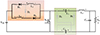 |
Fig. 3 Mode 1 opeartion. |
Mode 2: When the switch S1 is OFF, the energy stored in the inductors L1 and L2 decreases. The discharged inductors charge the capacitors C1 and C2. The inductor L3 supplies the energy to the load and hence the energy stored in the inductor decreases. The diodes D2, D4 and D5 are conducting and the diodes D1 and D3 are in revers biased condition. Figure 4 shows the equivalent circuit during mode 2. Steady-state waveforms of the modified converter are shown in Figure 5.
 |
Fig. 4 Mode 2 operation. |
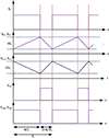 |
Fig. 5 Steady state waveforms of the modified CUK converter. |
2.3 Analysis of converter
For simplicity, it is considered that the designed converter is functioning in steady-state condition and all the capacitors are equal in size. During the mode 1, the inductor voltages VL1, VL2 and VL3 are expressed as below: (10)
(10)
 (11)
(11)
During the mode 2, the inductor voltages VL1, VL2, and VL3 are given as follows: (12)
(12)
 (13)
(13)
By applying the voltage second balance principle to all the inductors, we get the equations (14)
(14)
 (15)where K is the duty cycle of the converter. The voltage equation for the capacitors C1 and C2 is given as
 (16)
(16)
The converter static voltage gain in continuous conduction mode is given as (17)
(17)
The switch S1 is in OFF condition during mode 2. The voltage stress across the switch S1 and the diodes is given as (18)
(18)
 (19)
(19)
 (20)
(20)
 (21)
(21)
3 GHO based MPPT
Grass Hopper Optimization (GHO) is an exceptional member of the broad collection of swarm-based intelligence algorithms. GHO resembles grasshopper activity, and its life cycle is divided into two subcycles. Specifically, the nymph and adult cycles. Motion is restricted in the nymph cycle. It allows for more in-depth research of the local area. During the adult cycle, rapid quick jumps at stochastic intervals aid in avoiding predators and exploring new territory. The proportion of exploration and exploitation, as well as strong social interaction are important qualities. Optimization is done to minimize or maximize a cost function [29]. Figure 6 depicts the correcting pattern of individual particles in a GHO swarm. A comfort zone governs the distance between two consecutive particles influencing social interaction, attraction, and repulsion.
 |
Fig. 6 Correcting pattern of individual particles in a GHO swarm. |
3.1 GHO mathematical model
The PEMFC system has a nonlinear MPPT problem. Additionally, it becomes more complex due to the variation in cell temperature and MWC. To mitigate these technical issues, a sophisticated GHO mathematical is required. Figure 7 depicts the GHO flow chart with natural cubic spline model. The smooth and continuous nature of the spline improves the accuracy of power estimation, ensuring stable and rapid convergence to the optimal operating point of the PEMFC system. The trajectory of swarm particles in GHO is given by: (22)where P
i
represents the position of the ith GHO particle, A
i
denotes the advection of wind on each particle, G
i
is the gravity component of the ith GHO particle, and S
i
represents social interaction. To introduce randomness, the social interaction, gravity component, and transpiration are scaled by w1, w2, and w3, respectively.
(22)where P
i
represents the position of the ith GHO particle, A
i
denotes the advection of wind on each particle, G
i
is the gravity component of the ith GHO particle, and S
i
represents social interaction. To introduce randomness, the social interaction, gravity component, and transpiration are scaled by w1, w2, and w3, respectively. (23)
(23)
 |
Fig. 7 Flowchart of GHO MPPT. |
Social interaction, as defined in equation (24), plays a vital role in facilitating global solutions and information sharing within the swarm. (24)
(24)
where u
i,j
represents the separation between the ith and jth grasshoppers, and s denotes the function used to calculate social pressures, as defined by equation (25). (25)
(25)
Here, l
a
represents the length of attraction, and f denotes the degree of interaction. The function s(r) is carefully adjusted to balance the initial and final stages of the optimization process. The gravitational factor G
i
and wind attraction A
i
are expressed in equations (26) and (27), respectively. (26)
(26)
 (27)
(27)
or (28)
(28)
This GHO population eventually settles into its comfort zone, and as a result, it ceases to explore the search space. To solve optimization problems effectively, equation (28) is modified. The constants in equation (29) are changed to regulate speedy comfort zone achievement. (29)
(29)
where c denotes decreasing coefficient.
3.2 GHO for PEMFC MPPT
The GHO algorithm is employed to track the MPP due to its rapid convergence and minimal oscillations during steady-state operation. The initial population is randomly assigned values between 0 and 1, representing the duty cycle of the modified CUK converter. The search space is constrained between 0 and 1, with a maximum iteration count of 50 and 4 search particles. Equation (28) governs the update of GHO particle orientations. Each particle represents a potential solution, and the optimal duty cycle is determined as the output of the MPPT controller. The duty cycle corresponds to the GHO particle’s position, which is updated according to equation (30). (30)
(30)
where i and j denotes ith and jth GHO particles, d represents distance between them and t is the iteration index.
When there is a significant change in the operating conditions, GHO is re-initialized. The change in operating conditions is noticed when the relative change in power exceeds a certain threshold. (31)
(31)
The GHO algorithm is reinitialized when the power threshold, PFC, is exceeded. This behavior is observed in cases 2 and 3, where sudden changes at 0.3 s and 0.6 s lead to significant effects. To reduce computational time, a search-and-skip strategy is implemented. When a GHO particle, P
i
, explores an interval, it’s possible that another particle, like P3, has already scanned that region. If P
x
’s search overlaps with P
i
’s, P
i
can skip the overlapping area. Equation (30) checks for overlap between the ith particle and the rest of the population, determining the upper and lower bounds for the voltage examined by P
i
. (32)
(32)
where P m(i) and P m(x) denote the upper voltage limits of the intervals recorded by P i and P x .
The optimal operation region within the scanned intervals is determined by (33)
(33)
Equation (34) generates the effective GHO swarm particles and assigns the output to the most optimal particle as the global best solution. Following the assessment of the search space for Local Minima (LMs) and Candidate Heuristic Members (CHMs), it is anticipated that the Global Minimum (GM) will be discovered at Pgb. (34)
(34)
The pesudo code for the GHO MPPT controller with natural cubic spline model is presented in Algorithm 1.
Initialize GHO parameters: population size, max iterations, etc.
Ensure proper tracking of maximum power
Initialize input voltage (VFC), output voltage (Vout), power (P), desired load voltage (Vload), best power, and best settings.
Generate initial population of solutions. for each individual in the population do
end
Get Vin from the PEMFC system.
Get Vout for the individual.
Evaluate fitness as P = VFC × Vout.
repeat
| each individual in the population
until for do
end
;
Update individual position based on GHO algorithm.
Predict future power using cubic-spline-based prediction model.
Compute predicted power from the model.
for each individual in the population do
end
Get Vin from the PEMFC system.
Get Vout for the individual.
Evaluate fitness using predicted power as P = Vin × predictedpower.
Find the best individual in the current population.
If best individual’s fitness > best power then
end
Update best power and best settings.
Check if convergence criteria are met. if convergence criteria met then.
end
break. convergence or maximum iterations are reached
Apply best settings to the PEMFC system
4 Results and discussion
This section compares and evaluates the performance of the proposed GHO controller with NN and Adaptive Neuro Fuzzy Controller (ANFIS) controllers. To verify the efficiency of the proposed controller, the control techniques were implemented for a standalone high-voltage gain boost converter fed by a 1.26 kW PEMFC system. The system was examined under various operating conditions using the MATLAB Simulink platform over a period of 0.9 s.
4.1 Case 1: under Standard Operating Conditions (SOC)
The proposed GHO MPPT controller is tested at normal operating conditions (constant temperature and Constant MWC) and it is compared with NN and ANFIS controllers.
Figure 8 shows the DC link voltage and power of the PEMFC at the specified temperature. The PEMFC system generates a voltage of 23.5 V and delivers a power output of 1230 W. This voltage is then supplied to the modified CUK converter to meet the required load voltage. Similarly, Figure 9 displays the load voltage and output power of the standalone PEMFC system using the proposed GHO controller. The output voltage of the PEMFC, which is 24 V, is boosted to 220 V.
 |
Fig. 8 PEMFC output voltage and power at SOC. |
 |
Fig. 9 Output voltage and power at SOC with GHO controller. |
To validate the efficacy of the GHO controller, the output power is compared with the power obtained from the NN and ANFIS controllers in Figure 10. The proposed GHO controller achieves the highest output power of 1180 W, which is 4.42% higher than ANFIS and 7.27% higher than NN. This improvement reflects the superior power tracking capability of the GHO controller. Also, the GHO controller has the shortest settling time of 0.06 s, which is a 57% reduction compared to ANFIS (0.14 s) and a 71% reduction compared to NN (0.21 s). This highlights the enhanced dynamic response and faster convergence of the GHO controller, making it suitable for systems requiring rapid adaptation to changing operating conditions. The performance of the output power with different controllers is illustrated in Table 3.
 |
Fig. 10 Performance comparison of output power with different controllers at SOC. |
4.2 Case 2: dynamic temperature and constant MWC
To examine and validate the dynamic characteristics standalone PEMFC system with the GHO technique, the PEMFC temperature is varied in steps and MWC is kept constant at 12. Figure 11 depicts the temperature change scenarios in the PEMFC System. The temperature changes in the PEMFC system are accounted for as follows: (35)
(35)
 |
Fig. 11 Temperature changes during performance analysis. |
Figure 12 illustrates the output voltage and power of the PEMFC in relation to temperature changes. The system produces 810 W from 0 to 0.3 s, rising to 1210 W from 0.3 to 0.6 s, and subsequently dropping to 990 W from 0.6 to 0.9 s. Correspondingly, the output voltage of the PEMFC varies during these periods, measuring 19.75 V, 23.49 V, and 22.41 V, respectively.
 |
Fig. 12 PEMFC voltage and power for dynamic temperature conditions. |
Figure 13 presents the output voltage and power performance of the system using the GHO controller at different cell temperatures. During the initial phase (0.0–0.3 s), the system generates 785 W with a corresponding DC link output voltage of 192 V. Subsequently, between 0.3 and 0.6 s, the power output increases to 1170 W, accompanied by a DC link voltage of 233 V. Finally, from 0.6 to 0.9 s, the system produces 955 W with a DC link voltage of 206 V.
 |
Fig. 13 Output voltage and power at dynamic temperature conditions with GHO. |
Figure 14 compares the output power performance of the proposed GHO controller with other MPPT controllers, namely NN and ANFIS. The results demonstrate that the proposed controller exhibits superior tracking efficiency compared to the NN and ANFIS controllers. Table 4 provides a quantitative comparison of the output power achieved by different controllers under dynamic temperature conditions (300 K, 320 K, and 340 K). The proposed GHO controller consistently delivers the highest output power (785 W, 955 W, and 1170 W, respectively) and efficiency (up to 96.91%) while exhibiting minimal oscillations around the MPP, ensuring stable operation. In contrast, the NN and ANFIS controllers show moderate and high oscillations, with lower power and efficiency levels, highlighting their limitations in adapting to dynamic changes. The GHO controller’s reduced oscillations and faster convergence reflect its robust optimization strategy, enabling efficient and reliable performance across varying operating conditions.
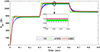 |
Fig. 14 Performance comparison with different controllers at dynamic temperature. |
4.3 Case 3: dynamic MWC and constant temperature
An additional scenario is examined to demonstrate the resilience of the proposed controller. In this particular case, the temperature of the PEMFC is kept at 240 K, while the MWC is systematically adjusted from 8 to 12. Figure 15 illustrates the variation in the PEMFC’s MWC as it transitions from 8 to 12 with a time frame of 0.3 s.
 |
Fig. 15 MWC changes during performance analysis. |
Figure 16 depicts the corresponding changes in the PEMFC’s output voltage and power in response to these varying MWC conditions. Notably, it is observed that the power output undergoes distinct shifts: starting at 810 W from 0 to 0.3 s, increasing to 1210 W from 0.3 to 0.6 s, and then decreasing to 990 W from 0.6 to 0.9 s. Similarly, the output voltage of the PEMFC demonstrates variations during these intervals, registering values of 19.75 V, 23.5 V, and 22.4 V, respectively.
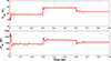 |
Fig. 16 PEMFC voltage and power for dynamic MWC conditions. |
Figure 17 exhibits the output voltage and power achieved by using GHO controller for varying MWC. The energy generated during specific time intervals is as follows: 785 W, 1170 W, and 955 W from 0.0 to 0.9 s in steps of 0.3 s. Meanwhile, the output voltage at the DC link reads 192 V, 233 V, and 206 V, respectively.
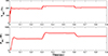 |
Fig. 17 Output voltage and power at dynamic MWC conditions with GHO. |
Figure 18 presents the response of output power with diverse MPPT controllers. It is discernible that the proposed GHO controller exhibits improved tracking efficiency compared to the NN and ANFIS controllers. Table 5 gives the output power comparison with different controllers at dynamic MWC conditions (MWC 8, MWC 10, and MWC 12). The proposed GHO controller consistently achieves superior performance, producing the highest output power (780 W, 950 W, and 1160 W for MWC 8, MWC 10, and MWC 12, respectively) and efficiency (up to 97.07%) while minimizing oscillations around the MPP. In contrast, NN and ANFIS show lower power output and efficiency levels, with NN demonstrating high oscillations and ANFIS showing moderate oscillations. The GHO controller’s ability to adapt to different MWC conditions with reduced oscillations and faster convergence emphasizes its robustness and optimization capabilities.
 |
Fig. 18 Performance comparison with different controllers at dynamic MWC. |
5 Conclusion
In this paper, an innovative GHO MPPT controller is designed for a standalone PEMFC system. The performance and reliability of the proposed controller have been rigorously tested under standard operating conditions, as well as in challenging scenarios involving sudden changes in cell temperature and partial pressure. The effectiveness of the GHO MPPT controller is benchmarked against the performance of the NN and ANFIS controllers. The results reveal that the proposed GHO MPPT controller not only achieves an impressive efficiency of 96.4% but also outperforms both the NN and ANFIS controller techniques. One of the significant advantages of the GHO controller is its ability to minimize oscillations within the system, thereby enhancing overall stability and reliability. This reduction in oscillations is critical for maintaining consistent performance and prolonging the lifespan of the PEMFC system.
Despite its advantages, the proposed GHO-based MPPT controller faces challenges such as high computational complexity and sensitivity to data quality. Additionally, improving convergence speed and ensuring scalability for higher-power PEMFC systems are crucial for broader adoption. Future work will focus on algorithm optimization for embedded systems, integration of adaptive machine learning techniques, and validation in large-scale PEMFC applications.
References
- Çelik Ö. (2024) Data-driven MPPT techniques for optimizing vehicular fuel cell performance in hybrid DC microgrid, Int. J. Hydrogen Energy 79, 715–727. [Google Scholar]
- Reddy K.J., Dash R., Subburaj V., Kumar B.H., Dhanamjayulu C., Blaabjerg F., Muyeen S.M. (2024) A stochastic variance reduction gradient-based GSO-ANFIS optimized method for maximum power extraction of proton exchange membrane fuel cell, Energy Convers. Manag. X 21, 100505. [Google Scholar]
- Reddy K.J., Sudhakar N., Saravanan S., Babu B.C. (2018) High step-up boost converter with neural network based MPPT controller for a PEMFC power source used in vehicular applications, Int. J. Emerg. Electr. Power. Syst. 19, 5, 20180015. [Google Scholar]
- Dandil B., Acikgoz H., Coteli R. (2024) An effective MPPT control based on machine learning method for proton exchange membrane fuel cell systems, Int. J. Hydrogen Energy 75, 344–353. [Google Scholar]
- Kumar K., Lakshmi Devi V., Dhanamjayulu C., Kotb H., ELrashidi A. (2024) Evaluation and deployment of a unified MPPT controller for hybrid Luo converter in combined PV and wind energy systems, Sci. Rep. 14, 1, 3248. [CrossRef] [Google Scholar]
- Rafikiran S., Devadasu G., Basha C.H., Tom P.M., Prashanth V., Dhanamjayulu C., Kumbhar A., Muyeen S.M. (2023) Design and performance analysis of hybrid MPPT controllers for fuel cell fed DC-DC converter systems, Energy Rep. 9, 5826–5842. [Google Scholar]
- Karami N., El Khoury L., Khoury G., Moubayed N. (2014) Comparative study between P&O and incremental conductance for fuel cell MPPT, in: International Conference on Renewable Energies for Developing Countries 2014, Beirut, Lebanon, 26–27 November, IEEE, pp. 17–22. [Google Scholar]
- Harrag A., Messalti S. (2017) Variable step size IC MPPT controller for PEMFC power system improving static and dynamic performances, Fuel Cells 17, 6, 816–824. [Google Scholar]
- Rezk H., Fathy A. (2020) Performance improvement of PEM fuel cell using variable step-size incremental resistance MPPT technique, Sustainability 12, 14, 5601. [CrossRef] [Google Scholar]
- Harrag A., Messalti S. (2018) How fuzzy logic can improve PEM fuel cell MPPT performances? Int. J. Hydrogen Energy 43, 1, 537–550. [Google Scholar]
- Rezk H., Aly M., Fathy A. (2021) A novel strategy based on recent equilibrium optimizer to enhance the performance of PEM fuel cell system through optimized fuzzy logic MPPT, Energy 234, 121267. [Google Scholar]
- Aly M., Rezk H. (2020) A differential evolution-based optimized fuzzy logic MPPT method for enhancing the maximum power extraction of proton exchange membrane fuel cells, IEEE Access 8, 172219–172232. [Google Scholar]
- Harrag A., Bahri H. (2017) Novel neural network IC-based variable step size fuel cell MPPT controller: performance, efficiency and lifetime improvement, Int. J. Hydrogen Energy 42, 5, 3549–3563. [Google Scholar]
- Kumar K., Tiwari R., Varaprasad P.V., Babu C., Reddy K.J. (2021) Performance evaluation of fuel cell fed electric vehicle system with reconfigured quadratic boost converter, Int. J. Hydrogen Energy 46, 11, 8167–8178. [Google Scholar]
- Reddy K.J., Sudhakar N. (2018) A new RBFN based MPPT controller for grid-connected PEMFC system with high step-up three-phase IBC, Int. J. Hydrogen Energy 43, 37, 17835–17848. [Google Scholar]
- Su Y., Ma K., Zheng S., Xue D., Li X. (2023) Ridgelet neural networks-based maximum power point tracking for a PEMFC connected to the network with interleaved boost converter optimized by improved satin bowerbird optimization, Energy Rep. 9, 4960–4970. [Google Scholar]
- Reddy K.J., Sudhakar N. (2019) ANFIS-MPPT control algorithm for a PEMFC system used in electric vehicle applications, Int. J. Hydrogen Energy 44, 29, 15355–15369. [Google Scholar]
- Hai T., Wang D., Muranaka T. (2022) An improved MPPT control-based ANFIS method to maximize power tracking of PEM fuel cell system, Sustainable Energy Technol. Assess. 54, 102629. [CrossRef] [Google Scholar]
- Ali Z.M., Al-Dhaifallah M., Al-Gahtani S.F., Muranaka T. (2023) A new maximum power point tracking method for PEM fuel cell power system based on ANFIS with modified manta ray foraging algorithm, Control Eng. Pract. 134, 105481. [Google Scholar]
- Basha C.H., Mariprasath T., Murali M., Rafikiran S. (2022) Simulative design and performance analysis of hybrid optimization technique for PEM fuel cell stack based EV application, Mater. Today Proc. 52, 290–295. [CrossRef] [Google Scholar]
- Percin H.B., Caliskan A. (2023) Whale optimization algorithm based MPPT control of a fuel cell system, Int. J. Hydrogen Energy 48, 60, 23230–23241. [Google Scholar]
- Ahmadi S., Abdi S., Kakavand M. (2017) Maximum power point tracking of a proton exchange membrane fuel cell system using PSO-PID controller, Int. J. Hydrogen Energy 42, 32, 20430–20443. [Google Scholar]
- Rana K.P.S., Kumar V., Sehgal N., George S. (2019) A novel dPdI feedback based control scheme using GWO tuned PID controller for efficient MPPT of PEM fuel cell, ISA Trans. 93, 312–324. [Google Scholar]
- Derbeli M., Barambones O., Silaa M.Y., Napole C. (2020) Real-time implementation of a new MPPT control method for a DC-DC boost converter used in a PEM fuel cell power system, Actuators 9, 4, 105. [CrossRef] [Google Scholar]
- Bahri H., Harrag A. (2021) Ingenious golden section search MPPT algorithm for PEM fuel cell power system, Neural Comput. Appl. 33, 14, 8275–8298. [CrossRef] [Google Scholar]
- Reddy K.J., Sudhakar N. (2018) High voltage gain interleaved boost converter with neural network based MPPT controller for fuel cell based electric vehicle applications, IEEE Access 6, 3899–3908. [Google Scholar]
- Reddy J., Sudhakar N. (2018) High voltage gain switched capacitor boost converter with ANFIS controller for fuel cell electric vehicle applications, in: 2018 2nd IEEE International Conference on Power Electronics, Intelligent Control and Energy Systems (ICPEICES), Delhi, India, 22–24 October, IEEE, pp. 465–470. [Google Scholar]
- Almalaq Y., Matin M. (2018) Three topologies of a non-isolated high gain switched-inductor switched-capacitor step-up CUK converter for renewable energy applications, Electronics 7, 6, 94. [Google Scholar]
- Mansoor M., Mirza A.F., Ling Q., Javed M.Y. (2020) Novel Grass Hopper optimization based MPPT of PV systems for complex partial shading conditions, Solar Energy 198, 499–518. [CrossRef] [Google Scholar]
All Tables
All Figures
|
Fig. 1 Standalone PEMFC system with GHO controller. |
| In the text | |
|
Fig. 2 Modified CUK converter. |
| In the text | |
|
Fig. 3 Mode 1 opeartion. |
| In the text | |
|
Fig. 4 Mode 2 operation. |
| In the text | |
|
Fig. 5 Steady state waveforms of the modified CUK converter. |
| In the text | |
|
Fig. 6 Correcting pattern of individual particles in a GHO swarm. |
| In the text | |
|
Fig. 7 Flowchart of GHO MPPT. |
| In the text | |
|
Fig. 8 PEMFC output voltage and power at SOC. |
| In the text | |
|
Fig. 9 Output voltage and power at SOC with GHO controller. |
| In the text | |
|
Fig. 10 Performance comparison of output power with different controllers at SOC. |
| In the text | |
|
Fig. 11 Temperature changes during performance analysis. |
| In the text | |
|
Fig. 12 PEMFC voltage and power for dynamic temperature conditions. |
| In the text | |
|
Fig. 13 Output voltage and power at dynamic temperature conditions with GHO. |
| In the text | |
|
Fig. 14 Performance comparison with different controllers at dynamic temperature. |
| In the text | |
|
Fig. 15 MWC changes during performance analysis. |
| In the text | |
|
Fig. 16 PEMFC voltage and power for dynamic MWC conditions. |
| In the text | |
|
Fig. 17 Output voltage and power at dynamic MWC conditions with GHO. |
| In the text | |
|
Fig. 18 Performance comparison with different controllers at dynamic MWC. |
| In the text | |
Current usage metrics show cumulative count of Article Views (full-text article views including HTML views, PDF and ePub downloads, according to the available data) and Abstracts Views on Vision4Press platform.
Data correspond to usage on the plateform after 2015. The current usage metrics is available 48-96 hours after online publication and is updated daily on week days.
Initial download of the metrics may take a while.