")
")
| Issue |
Sci. Tech. Energ. Transition
Volume 81, 2026
Enabling Technologies for the Integration of Electrical Systems in Sustainable Energy Conversion
|
|
|---|---|---|
| Article Number | 8 | |
| Number of page(s) | 11 | |
| DOI | https://doi.org/10.2516/stet/2026004 | |
| Published online | 06 April 2026 | |
Regular Article
Design and manufacturing of axial flux permanent magnet machines for electric vehicle applications
IFP Energies nouvelles Institut Carnot IFPEN Transports Energie, 1 et 4 avenue de Bois-Préau, 92852 Rueil-Malmaison, France
* Corresponding author: This email address is being protected from spambots. You need JavaScript enabled to view it.
Received:
15
May
2025
Accepted:
28
January
2026
Abstract
This paper presents the design and prototyping of an open-slot, 18-slot, 12-pole, Axial-Flux, Permanent-Magnet (AFPM) machine that meets the typical requirements of electric vehicles. A multiphysics design approach was used to consider mechanical and thermal constraints during the design stage. The electromagnetic design is based on a combination of 2D and 3D Finite Element Analysis (FEA) approaches. Segmenting the rotor and optimizing the rotor disc material reduces rotor losses. This provides a balanced compromise between eddy current losses and manufacturing costs. The designed machine was manufactured and tested on a test bench under both no-load and load conditions. Experimental results, such as Back Electromotive Force (Back EMF), torque as a function of current, magnet temperature, and torque and power versus speed curves, are compared with simulation results. The impact of the manufacturing process on performance, especially iron losses, is investigated. For this purpose, the iron losses are assessed using the stator yoke of the axial flux machine in both the torus configuration test and an Epstein frame. These specific iron losses are then used to evaluate iron losses via 3D FEA. Several configurations are tested to evaluate different no-load losses, such as mechanical losses, magnet losses, rotor holder losses, and stator iron losses, as well as AC losses due to the proximity effect caused by the external magnetic field generated by the rotation of the magnets, in order to compare the calculated iron losses obtained by 3D FEA with the measured ones. Rotor losses in the magnet and rotor holder are evaluated by measuring the rotor temperature using an infrared sensor.
Key words: Axial flux machines / Multiphysics design / Finite element analysis / Tooth coil / Open slot / Rotor losses / Prototype / Test / Bench
© The Author(s), published by EDP Sciences, 2026
 This is an Open Access article distributed under the terms of the Creative Commons Attribution License (https://creativecommons.org/licenses/by/4.0), which permits unrestricted use, distribution, and reproduction in any medium, provided the original work is properly cited.
1 Introduction
Axial flux permanent magnet machines are well known for their high power and torque densities, making them an attractive competitor to conventional radial flux Permanent Magnet (PM) machines, especially for applications where axial length is limited [1–3]. There are different configurations of AFPM machines, such as: Single Stator-Single Rotor (SSSR), Double Stator-Single Rotor (DSSR), Single Stator-Double Rotor (SSDR), and Yokeless and Segmented Armature (YASA) [4]. This work focuses on the DSSR configuration with tooth coil windings and an open slot. Designing a DSSR for automotive traction is a challenge, particularly in terms of mechanical and thermal aspects. In fact, the tooth coil windings are an attractive solution for these types of machines, as they have a smaller end winding compared to traditional distributed windings and save on manufacturing costs [5]. In principle, such windings are only possible in machines where rotors have a very low conductivity. The disadvantage of tooth coils is that the stator current linkage produces various sub- and super- space-harmonic components in the air gap flux density. These harmonic components cause hysteresis and eddy-current losses. Also, the large open slot induces space harmonics harmonics, increasing rotor losses even in no-load conditions [6]. As a result, machine performance decreases due to high rotor losses, especially if the rotor is not laminated and the magnets are not segmented. Moreover, the temperature of the permanent magnet rises, which can lead to irreversible demagnetization. After the winding operation, motor slots are usually closed, for instance with some glass-fiber-based wedge material, to prevent the coils from falling or interference caused by the air gap or the rotor. Glass-fiber wedges have been used for several years, and they have several advantages: they are mechanically strong enough, their relative permeability is equal to 1, and they do not cause heat or other losses. To reduce rotor losses, other materials tested for closing the slot opening include Magnoval and Soft Magnetic Composite (SMC) materials [7, 8]. The permeability of Magnoval varies between 2 and 3, and it depends on the magnitude of flux density. Magnoval is made of glass cloth, iron powder, and a high-temperature-resistant epoxy resin. SMC materials have a permeability of up to 850. Hence, from the machine design perspective, these materials are helpful as they can provide a path for the main flux and reduce rotor losses [5]. Therefore, to enhance the thermal performance of the machine, these considerations must be taken into account in the design stage. On the other hand, axial rotor misalignment produces an axial force that deforms the rotor disc [9]. To take account of these mechanical and thermal constraints, a multiphysics design approach, considering electromagnetic, thermal, and mechanical aspects is advisable during the machine design phase. The aim of this article is to design and manufacture an AFPM machine with tooth coil windings and open slots. The design procedure is based on a multiphysics approach to take into account thermal and mechanical constraints.
During the design phase, reducing rotor losses is achieved through magnet segmentation and selecting the rotor disc material. This work also aims to demonstrate the impact of the manufacturing process on performance, particularly with regard to iron losses.
This paper is divided into five sections. The first section presents the electromagnetic design of a DSSR-AFPM machine with 18 slots and 12 poles that meets electric vehicle requirements. The design procedure combines 2D and 3D approaches. The second section minimizes rotor losses. This is achieved through magnet segmentation and selecting the rotor disc material. The third section discusses the mechanical and thermal design of the machine. It also analyzes the impact of axial rotor misalignment and thermal behavior. The fourth section is dedicated to prototyping and comparing experimental measurements with 3D FEA results. The final section examines the effect of the manufacturing process on iron losses.
2 Design of an AFPM machine using 2D and 3D FEA
In this part, the electromagnetic design of an 18-slot-12-pole DSSR-AFPM meeting the requirements of an electric vehicle is carried out. The design procedure is based on the combination of 2D and 3D approaches.
2.1 Specifications
The design specifications of the benchmark model described in [10]. have been used. The benchmark AFPM machine is a DSSR structure, and its main specifications are given in Table 1. The purpose is not to compare one to the other, but to have a set of requirements representative of an electric vehicle. The DSSR-AFPM is designed to meet these specifications.
Main specifications.
2.2 Electromagnetic design
The 2D approach is used during the first design stage. The design procedure is detailed in our previous work [11–14]. Figure 1 shows one-sixth of the 3D parts of the designed machine and its equivalent 2D parts.
 |
Figure 1 1/6 of the geometrical model and tooth coil winding distribution: a) 3D model and b) 2D model. |
In the design strategy, different rotor/slot combinations of the DSSR-AFPM machine are compared. Several slot-pole configurations of the machine with the same number of total Ampere turns and the same amount of permanent magnet are designed. The main characteristics of these configurations are given in Table 2. Electrically, the maximum of the peak stator phase current is limited to 700 A line inverter peak current, and the DC bus voltage is fixed to 400 V. Designed machines will be thermally limited to a current density of 21 A/mm2 with a slot fill factor fixed to 51%.
Main characteristics of the designed machines.
The torque-speed curves of the designed machines are shown in Figure 2. As we can see, the 18-slot/16-pole combination has higher torque than the other combination. This is due to its higher winding factor. Despite its slightly lower winding factor, the 18-slot/12-pole combination has good torque-speed characteristics, especially in the flux weakening region. In addition, having a lower winding factor leads to a minimum rotor losses and a well-balanced high order mode with the lowest amplitude of mechanical deformation [15]. For this reason, this configuration was chosen to be investigated in depth with a 3D tool and manufactured. Figure 3 gives the torque and power characteristics as a function of the rotational speed calculated by 3D FEA.
 |
Figure 2 Torque-speed curves of DSSR machines with different slot-pole configurations obtained by 2D FEA. |
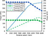 |
Figure 3 Torque and power characteristics as function of speed. |
3 Rotor losses reduction
The impact of the number of PM segments in the radial direction (Nrs = 5, 10, and 15) on the eddy current losses is investigated using 3D FEA. For Nrs = 10, the impact of the number of PM segments in the tangential direction (Nts = 1, 2, and 4) on the eddy current losses is also calculated. An electrical insulation of 0.15 mm width is set around each magnet segment. The impact of the magnet segmentation on torque, stator iron losses, and efficiency for the designed machine is given Table 3. The magnet segmentation slightly reduces the electromagnetic torque (5% reduction with Nrs = 15) as well as the iron losses in the stator. This is due to the reduced magnet mass with segmentation. For Nrs = 15, the efficiency is increased by 0.66% compared to that calculated with Nrs = 5. This will have a considerable impact on the machine’s thermal performance, especially on the rotor temperature.
Impact of PM radial and tangential segmentation on machine losses and efficiency.
Figures 4a and 4b show the eddy-current distribution, respectively, in the PMs for a radial segmentation of Nrs = 15 and in the magnet rotor holder. As can be seen, the highest current densities are found on the arms of the magnet rotor holder, especially in front of the magnets. So, even if the rotor disc material is an electrical conductor, the eddy current losses can be reduced by optimizing the shape of the arms.
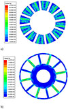 |
Figure 4 Current density distribution a) in the magnets b) rotor disc. |
Table 4 shows the rotor losses and the efficiency calculated by 3D FEA at the rated operating point corresponding to a rotational speed of 6500 rpm, and a current phase of 250 A. The magnet segmentation slightly reduces the electromagnetic torque, with approximately a 5% reduction for Nrs = 15. Note that these losses were calculated for different materials used in the magnet rotor holder. As can be seen, the eddy current losses in the rotor increase with the electrical conductivity of the material, and these losses have a significant impact on the efficiency. So, to minimize the rotor losses, each magnet is segmented into 15 segments, and the magnet rotor holder is made of stainless steel.
Losses as function of the rotor disc materials.
4 Mechanical and thermal design
4.1 Analysis of axial force and axial deformation
At the operating point of 700 A of current phase and 4500 rpm (Fig. 3). The axial force due to rotor misalignment is evaluated by 3D FEA at each rotor position, for different air gap values (E1: airgap of the stator1, E2: airgap of the stator2). Figure 5 shows the z-component of the axial unbalanced force. As shown, the axial misalignment of the rotor has a significant effect on the axial unbalanced force. Note that, in the case where the stator air gap (E1) is equal to that of stator 2 (E2), the axial force is almost zero.
 |
Figure 5 Axial force as a function of axial misalignment of the rotor. |
A 3D mechanical analysis is carried out applying an axial force of 150 N to the rotor (equivalent force for a 20% axial misalignment of the rotor). The study is carried out considering the rotor disc made of stainless steel. The maximum axial deformation of the rotor in the axial direction is about 0.035 mm (Fig. 6). In this application, the magnets are glued in the rotor pockets. A 3D mechanical analysis considering the effects of centrifugal force is carried out, including the impact of the adhesive on shear forces. However, the results of this study are not reported here. In conclusion, the design of the rotor is both feasible and reliable.
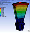 |
Figure 6 Axial deformation of the rotor. |
4.2 Thermal analysis
The temperature is critical for the functionality and performance of an electric machine, as the properties of both insulation and permanent magnet strongly depend on it. In this application, the cooling system uses water jacket cooling. From the CFD simulation, the Heat Transfer Coefficient (HTC) of the water jacket is calculated. For a water flow rate of 6 L/min, the HTC of the water jacket is 1700 W/m2/K at a water temperature of 30 °C. Since the frame is not shrink-fitted, a thermal contact resistance is considered between the stator yoke and the cooling jacket, and its value is set to 450 W/m2/K. The same value is applied to account for the thermal resistance between the magnets and their holder. Finally, the thermal resistance between the winding and the stator iron is set to 250 W/m2/K. The thermal analysis is carried out using 3D Ansys Mechanical. Temperature distribution is estimated using losses calculated from electromagnetic analysis.
The temperature distribution for the rated operating point corresponding to a rotational speed of 4500 and a torque of 140 N m is shown in Figure 7. This corresponds approximately to 40% of the maximum torque. The highest temperature, 132 °C, is reached by the magnets. Based on this analysis, we can conclude that continuous power is about 40% of the maximum power.
 |
Figure 7 Temperature distribution at 140 N m and 4500 rpm a) rotor b) stator. |
5 Comparison between simulation and experimental results
5.1 Prototype and construction
A DSSR-AFPM machine with 18 slots and 12 poles, previously designed, has been constructed to gain practical experience in the manufacturing of the tooth coil machine and to verify the computed losses. The pre-assembled prototype machine is shown in Figure 8. A 1.5 mm diameter round wire is used for winding the stator. The slot fill factor is about 42% compared to the 51% used during the design phase. The total number of turns per coil is therefore 48, compared to the 54 turns initially planned. To ensure a meaningful comparison between the measurements and the 3D FEA calculations, the same number of turns per coil –48– is used.
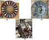 |
Figure 8 Prototype a) stator with tooth coils, b) rotor disc with magnets, (c) complete prototype machine. |
5.2 Experimental setup
The performance of the designed motor is evaluated experimentally. Figure 9 illustrates a photograph of the designed prototype mounted on the test rig.
 |
Figure 9 Test bench. |
5.2.1 No-load condition
Figure 10 shows the comparison between the back-EMF at 1000 rpm obtained by the measurement and that obtained by the 3D FEA. Both back-EMFs are nearly identical. The harmonic content of the measured and the calculated back EMF is also presented in Figure 11. The same harmonic contents are obtained by both simulation and experimental measurement. In this machine, the back-EMF spectrum has both even and odd harmonics. However, the odd harmonic content dominates.
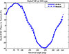 |
Figure 10 Back-EMF waveforms at 1000 rpm. |
 |
Figure 11 Harmonic content at 1000 rpm. |
5.2.2 Loaded condition
During the loading test, the prototype operates as a motor. The torque is measured at 1000 rpm for different phase current values ranging from 20 to 400 A. The cooling water temperature is set to 25 °C.
The variation in torque as a function of current is calculated by 3D FEA for a magnet temperature of 25 °C. The torque calculated is the electromagnetic torque. The mechanical torque on the shaft can be approximated by subtracting the no-load torque at 1000 rpm from the electromagnetic torque. At 1000 rpm, the no-load torque varies from 1.44 to 2.13 N m. As shown in Figure 12, the maximum deviation is approximately 3.5%. Figure 13 shows that magnet temperature has a significant impact on torque. An increase in magnet temperature by 75 °C results in a torque reduction of 7%. Figures 14 and 15 present a comparison between the measured and simulated torque-speed characteristics for two currents of 700 A and 250 A. As can be observed, the simulated torque-speed curves closely match the measured curves.
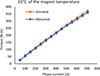 |
Figure 12 Measured torque at 1000 rpm. |
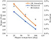 |
Figure 13 Measured torque at 1000 rpm as function of the magnet temperature. |
 |
Figure 14 Torque and power characteristics as function of speed at 250 A. |
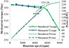 |
Figure 15 Torque and power characteristics as function of speed at 700 A. |
6 Investigation of the impact of the manufacturing process on iron losses
To demonstrate the effect of the manufacturing process on iron losses, DSSR-AFPM stators are manufactured both through punching and machining. These stators were subject to a torus test to measure specific losses, which were then used to evaluate stator-iron losses via 3D FEA. Additionally, stator iron losses were also measured using various test and measurement techniques.
6.1 Specific iron losses measurements
As shown in Figure 16, the stator yoke of the axial flux machine is used for a torus test. The primary and secondary Figure 13. Measured torque at 1000 rpm as function of the magnet temperature, Figure 14. Torque and power characteristics as function of speed at 250 A. windings are wound around the stator yoke. Specific losses as a function of frequency and flux density were measured on the stator of the DSSR-AFPM machine. The curves of specific losses versus frequency and flux density, shown in Figure 17, were obtained from this test. The specific losses obtained using the Epstein frame are also shown in Figure 17. As shown, the manufacturing process has a significant impact on iron losses, with the specific losses measured using the torus test up to twice as high as those measured using the Epstein frame.
 |
Figure 16 The DSSR-AFPM machine stator used as a torus test. |
 |
Figure 17 The specific losses as function of the frequency. |
6.2 Separation of the measured no load-losses
No-load losses are usually generated when a machine is running at open circuit; the losses include the following components: mechanical losses, consisting of bearing losses and aerodynamic losses; eddy current rotor disk losses; stator iron losses, and AC copper losses due to the proximity effect. Several experimental configurations have been realized and tested to separate the different losses. The different configurations used to separate the no-load losses are summarized in Table 5. To evaluate the friction torque and therefore, the no-load losses, all the configurations are driven as an electric generator. Note that some losses are measured directly, while others, such as the AC losses and iron losses, were deduced.
Different configurations to separate the No-Load Losses.
6.2.1 Measurement of rotor disc losses
Rotor disk losses are caused by eddy current losses in the magnets and rotor holder. The method used is based on [16] Magnet losses are determined by measuring the initial temperature rise rate of the magnets from a thermally uniform initial condition. When an element is subjected to a unit step function of heat generation under thermally uniform and stationary conditions, the temperature rise of the element is proportional to the heat generation rate, as given by equation (1).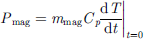 (1)where Pmag is the heat generation rate mmag (W), mmag is the mass (kg), Cp is the heat capacity (J kg−1 °C−1), and dT/dt is the initial rate of temperature rise of the element (°C/s). In this study, the magnets were weighed to determine their mass, and the heat capacity was taken from the manufacturer’s datasheet. The aim of the following method is therefore to determine dT/dt at t = 0.
Configuration 3 is used to measure the rotor temperature with an infrared sensor on the outer diameter of the rotor. For each speed, the rotor temperature is also estimated using the measured back-EMF. Both methods give the same trend for the rotor temperature. This indicates that the temperature of the magnets and the rotor holder follows the same trend. Therefore, the same curve can be used to estimate rotor holder losses. Magnet losses are estimated by measuring the initial temperature rise rate of the magnets from a thermally uniform initial condition. Figure 18 shows the normalized magnet temperature rise as a function of time for each rotation speed. The gradient increases with the rotation speed. The evolution of the rotor temperature gradient as a function of the rotation speed is shown in Figure 19. Using equation (1), the eddy current losses of the magnets and the rotor holder are measured (Fig. 20).
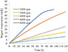 |
Figure 18 The normalized magnet temperature rise. |
 |
Figure 19 The evolution of the temperature gradient as a function of the speed. |
 |
Figure 20 Measured no-load rotor losses where: Mechanical_M: measured mechanical losses, PM_M: measured magnets losses, Holder_M: measured rotor holder losses. |
Figure 20 shows the different rotor losses measured with Config. 1 and Config. 3. As can be seen, the eddy current losses in the magnets are close to those of the rotor holder. This is mainly because their masses are very close (2.10 kg for the magnets vs. 1.82 kg for the rotor holder). The mechanical losses, consisting of bearing losses and aerodynamic losses, are the lowest.
6.2.2 AC losses
At no-load, a configuration with a tooth winding and an open slot causes AC losses due to the proximity effect. The winding AC losses are measured by subtracting the no-load losses measured with Config. 2 from those measured with Config. 3.
Figure 21 shows the AC losses as a function of rotation speed. As can be seen, they exceed 1 kW at 8000 rpm (900 Hz), significantly affecting the efficiency and thermal performance of the machine.
 |
Figure 21 The measured AC losses were: AC_M: measured AC losses. |
6.2.3 Stator iron losses
At this stage, all losses except stator iron losses have been determined. These losses can be deducted by subtracting directly measured losses from total losses. Figure 22 shows the measured stator iron losses, comparing them to the losses calculated by 3D FEA. Stator iron losses (Core_Sim_torus) were calculated using 3D FEA (Fig. 22) and compared to those calculated using the specific losses obtained (Core_Sim_Epstein). Unlike the Epstein frame method, the torus test provided an accurate iron loss prediction. Rolling the electrical steel sheet significantly affects iron losses, emphasizing the need for accurate characterization of the stator to incorporate this effect into the model for better predictions of iron losses.
 |
Figure 22 Stator iron losses measured by differentiation where: Core_M: measured stator iron losses, Core_Sim_torus and Core_Sim_Epstein are simulated stators iron losses. |
7 Conclusion
In this paper, the design and prototyping of an 18 slot – 12 pole DSSR-AFPM machine that meets a set of automotive specifications are presented. Tooth coil windings with open slots induce space harmonics, increasing the rotor losses even under no-load conditions. To address this, rotor losses are reduced during the design stage through magnet segmentation and material selection:
-
The magnet is segmented into 15 segments.
-
For manufacturing reasons, a disc rotor with stainless steel is chosen, although a fibre-glass disc rotor would offer better performance.
In the design procedure, mechanical and thermal stresses are considered to ensure:
-
The mechanical integrity of the rotor structure, subjected to axial force due to both axial offset of the rotor and centrifugal forces at high speed.
-
Operation at continuous power equal to 40% of the maximum power.
The comparison of experimental and simulation results shows accurate predictions of Back-EMF, torque, and torque/ power versus speed characteristics.
The manufacturing process significantly impacts iron losses. Rolling the electrical steel sheet significantly increases iron losses, which can be twice as high as those measured using the Epstein frame.
References
- Cavagnino A., Lazzari M., Profumo F., Tenconi A. (2002) A comparison between the axial flux and the radial flux structures for PM synchronous motors, IEEE Trans. Indus. Appl. 38, 6, 1517–1524. [Google Scholar]
- Gieras J.F., Wang R.J., Kamper M.J. (2008) Axial flux permanent magnet brushless machines, Springer Science & Business Media. [Google Scholar]
- Husain T., Tekgun B., Sozer Y., Hamdan M. (2017, May) Comparison of axial flux machine performance with different rotor and stator configurations, in 2017 IEEE International Electric Machines and Drives Conference (IEMDC), IEEE, pp. 1–8. [Google Scholar]
- Parviainen A., Niemela M., Pyrhonen J. (2004) Modeling of axial flux permanent-magnet machines, IEEE Trans. Indus. Appl. 40, 5, 1333–1340. [Google Scholar]
- Lindh P.M., Pyrhönen J.J., Ponomarev P., Vinnikov D. (2013, November) Influence of wedge material on losses of a traction motor with tooth-coil windings, in: IECON 2013–39th Annual Conference of the IEEE Industrial Electronics Society, IEEE, pp. 2941–2946. [Google Scholar]
- Alberti L., Fornasiero E., Bianchi N., Bolognani S. (2011) Rotor losses measurements in an axial flux permanent magnet machine, IEEE Trans. Energy Convers. 26, 2, 639–645. [Google Scholar]
- https://www.hoganas.com on 4.5.2012. [Google Scholar]
- https://www.stenbacka.fi on 4.5.2012. [Google Scholar]
- Lai J., Li J., Xiao T. (2020) Design of a compact axial flux permanent magnet machine for hybrid electric vehicle, IEEE Trans. Indus. Electron. 68, 8, 6630–6639. [Google Scholar]
- Lampérth M.U., Malloy A.C., Mlot A., Cordner M. (2015) Assessment of axial flux motor technology for hybrid powertrain integration, World Electric Vehicle J. 7, 2, 187–194. [Google Scholar]
- Abdelli A., Gilson A., Chareyron B., Zito G. (2023, April) Combination of 2D and 3D Finite Element Models in the Design of Axial Flux Permanent Magnet Machines for Electric Vehicle Applications, in: 2023 IEEE Workshop on Electrical Machines Design, Control and Diagnosis (WEMDCD), IEEE, pp. 1–6. [Google Scholar]
- Gulec M., Aydin M. (2018) Implementation of different 2D finite element modelling approaches in axial flux permanent magnet disc machines, IET Electric Power Appl. 12, 2, 195–202. [Google Scholar]
- Taran N., Ardebili M. (2014, June) A novel approach for efficiency and power density optimization of an axial flux permanent magnet generator through genetic algorithm and finite element analysis, in: 2014 IEEE 23rd International Symposium on Industrial Electronics (ISIE), IEEE, pp. 709–714. [Google Scholar]
- Taran N., Heins G., Rallabandi V., Patterson D., Ionel D.M. (2020) Evaluating the effects of electric and magnetic loading on the performance of single-and double-rotor axial-flux PM machines, IEEE Trans. Indus. Appl. 56, 4, 3488–3497. [Google Scholar]
- Aslan B., Semail E., Korecki J., Legranger J. (2011, November) Slot/pole combinations choice for concentrated multiphase machines dedicated to mild-hybrid applications, in IECON 2011–37th Annual Conference of the IEEE Industrial Electronics Society, IEEE, pp. 3698–3703. [Google Scholar]
- Malloy A.C., Martinez-Botas R.F., Lamperth M. (2014) Measurement of magnet losses in a surface mounted permanent magnet synchronous machine, IEEE Trans. Energy Convers. 30, 1, 323–330. [Google Scholar]
All Tables
Impact of PM radial and tangential segmentation on machine losses and efficiency.
All Figures
|
Figure 1 1/6 of the geometrical model and tooth coil winding distribution: a) 3D model and b) 2D model. |
| In the text | |
|
Figure 2 Torque-speed curves of DSSR machines with different slot-pole configurations obtained by 2D FEA. |
| In the text | |
|
Figure 3 Torque and power characteristics as function of speed. |
| In the text | |
|
Figure 4 Current density distribution a) in the magnets b) rotor disc. |
| In the text | |
|
Figure 5 Axial force as a function of axial misalignment of the rotor. |
| In the text | |
|
Figure 6 Axial deformation of the rotor. |
| In the text | |
|
Figure 7 Temperature distribution at 140 N m and 4500 rpm a) rotor b) stator. |
| In the text | |
|
Figure 8 Prototype a) stator with tooth coils, b) rotor disc with magnets, (c) complete prototype machine. |
| In the text | |
|
Figure 9 Test bench. |
| In the text | |
|
Figure 10 Back-EMF waveforms at 1000 rpm. |
| In the text | |
|
Figure 11 Harmonic content at 1000 rpm. |
| In the text | |
|
Figure 12 Measured torque at 1000 rpm. |
| In the text | |
|
Figure 13 Measured torque at 1000 rpm as function of the magnet temperature. |
| In the text | |
|
Figure 14 Torque and power characteristics as function of speed at 250 A. |
| In the text | |
|
Figure 15 Torque and power characteristics as function of speed at 700 A. |
| In the text | |
|
Figure 16 The DSSR-AFPM machine stator used as a torus test. |
| In the text | |
|
Figure 17 The specific losses as function of the frequency. |
| In the text | |
|
Figure 18 The normalized magnet temperature rise. |
| In the text | |
|
Figure 19 The evolution of the temperature gradient as a function of the speed. |
| In the text | |
|
Figure 20 Measured no-load rotor losses where: Mechanical_M: measured mechanical losses, PM_M: measured magnets losses, Holder_M: measured rotor holder losses. |
| In the text | |
|
Figure 21 The measured AC losses were: AC_M: measured AC losses. |
| In the text | |
|
Figure 22 Stator iron losses measured by differentiation where: Core_M: measured stator iron losses, Core_Sim_torus and Core_Sim_Epstein are simulated stators iron losses. |
| In the text | |
Current usage metrics show cumulative count of Article Views (full-text article views including HTML views, PDF and ePub downloads, according to the available data) and Abstracts Views on Vision4Press platform.
Data correspond to usage on the plateform after 2015. The current usage metrics is available 48-96 hours after online publication and is updated daily on week days.
Initial download of the metrics may take a while.