")
")
| Issue |
Sci. Tech. Energ. Transition
Volume 80, 2025
Decarbonizing Energy Systems: Smart Grid and Renewable Technologies
|
|
|---|---|---|
| Article Number | 19 | |
| Number of page(s) | 17 | |
| DOI | https://doi.org/10.2516/stet/2024110 | |
| Published online | 29 January 2025 | |
Review Article
Empirical analysis of control models for different converter topologies from a statistical perspective
Dayananda Sagar University, DSU Main Campus Devarakaggalahalli, Harohalli, Kanakapura Road, Ramanagara Dt., Bengaluru 562 112, India
* Corresponding author: This email address is being protected from spambots. You need JavaScript enabled to view it.
Received:
2
July
2024
Accepted:
19
December
2024
Abstract
Converter topologies including SEPIC, ZETA, etc. are controlled via selection of capacitive and inductive components, which assists in improving its conversion efficiency for different type of loads. A wide variety of such models are proposed by researchers, that include, but are not limited to, bioinspired techniques for rating selection, Neural Network based models for load-based component selection, etc. Each of these models vary in terms of their internal operating characteristics, and showcase highly variant quantitative and qualitative performance under different loads. This variation increases the ambiguity of model selection under context-specific applications. To reduce this ambiguity, a detailed discussion about these models in terms of their context-specific nuances, qualitative advantages, deployment-specific limitations, and functional future scopes is described in this text. Based on this discussion, researchers will be able to identify optimal models for their application-specific use cases. It was observed that bioinspired models and incremental learning techniques assists in improving control performance for efficiency-aware use cases. This text also compares the evaluated models in terms of their conversion efficiency, cost of deployment, delay needed for control, scalability and computational complexity under different scenarios. Based on this comparison, researchers will be able to identify optimized models for their performance-specific deployments. This text further proposes evaluation of a novel Converter Control Rank Metric (CCRM) that combines these metrics, and assists in identification of converter control models that showcase high conversion efficiency with low delay, low complexity, high scalability, and low deployment costs. This will allow readers to select and modify optimized models for their context-specific use cases. The main reason of conduction this research is how to dispel the ambiguity in the process of choosing the suitable control models corresponding to the appropriate converter topology that can satisfy a set of particular application requirements. Even though, there are various control models available, these characteristics often become a barrier to their straightforward adoption for applications that are performance critical. This paper fills this void by providing a thorough experimental comparison of these models, resulting in the creation of the CCRM metric. The proposed framework gives researchers and Practitioners a unitary decision making high level tool for finding, tailoring and enhancing the performance of control models necessary for improved conversion efficiency, increased scalability and cost effectiveness in the deployment.
Key words: Converter / Control / Bioinspired / Machine / Learning / Q-Learning / Efficiency / Error
© The Author(s), published by EDP Sciences, 2025
 This is an Open Access article distributed under the terms of the Creative Commons Attribution License (https://creativecommons.org/licenses/by/4.0), which permits unrestricted use, distribution, and reproduction in any medium, provided the original work is properly cited.
Nomenclature: Parameters
P: Power output (W)
Pin: Input power (W)
Pout: Output power (W)
V: Voltage (V)
Vin: Input voltage (V)
Vout: Output voltage (V)
I: Current (A)
Iin: Input current (A)
Iout: Output current (A)
Trise: Rise time (s)
Tfall: Fall time (s)
Tcycle: Time for one operating cycle (s)
η: Conversion efficiency (%)
Tdelay: Control delay (s)
Cdeploy: Cost of deployment ($)
Tswitch: Switching period (s)
D: Duty cycle
Z:
Impedance ( )
)
Q: Quality factor
E: Energy (J)
F: Force (N)
R:
Resistance ( )
)
L: Inductance (H)
C: Capacitance (F)
F: Switching frequency (Hz)
Variables
x: State variable (e.g., voltage or current)
u: Control input
y: Output variable
e: Error signal (e.g., e = ydesired − yactual)
Δ: Incremental change (e.g., ΔV: Voltage variation)
t: Time (s)
ω: Angular frequency (rad/s)
ϕ: Phase angle (rad)
α: Control gain
k p : Proportional gain
k i : Integral gain
k d : Derivative gain
λ: Learning rate for bioinspired or adaptive algorithms
μ: Damping coefficient
γ: Scaling factor for computational complexity
σ: Signal noise
Sets
 :
Set of control models (e.g., bioinspired, neural network-based, etc.)
:
Set of control models (e.g., bioinspired, neural network-based, etc.)
 :
Set of scenarios or load conditions
:
Set of scenarios or load conditions
 :
Set of converter topologies (e.g., SEPIC, ZETA, etc.)
:
Set of converter topologies (e.g., SEPIC, ZETA, etc.)
 :
Set of performance metrics (e.g., efficiency, cost, delay)
:
Set of performance metrics (e.g., efficiency, cost, delay)
 :
Set of load types (e.g., resistive, inductive, capacitive)
:
Set of load types (e.g., resistive, inductive, capacitive)
 :
Set of tuning parameters for control systems
:
Set of tuning parameters for control systems
 :
Set of capacitive components
:
Set of capacitive components
 :
Set of inductive components
:
Set of inductive components
 :
Set of resistive elements in the system
:
Set of resistive elements in the system
 :
Set of voltage levels for multilevel converters
:
Set of voltage levels for multilevel converters
 :
Set of frequencies for harmonic analysis
:
Set of frequencies for harmonic analysis
1 Introduction
There are several uses for two-stage single-phase rectifiers and inverters in low- to medium-power conversions. This two-stage single-phase rectifier (Fig. 1a) can convert an Alternating Current (AC) input voltage into regulated Direct Current (DC), which may then be used to power a DC microgrid or other DC loads (a). The circuit’s starting point is an AC-DC rectifier, and its finishing point is a DC-DC converter. The DC input voltage in Figure 1b [1–4] is converted into a high-quality AC voltage that may be used to power an AC load or added to an AC power grid. A DC-DC converter is situated at the beginning, and a DC-AC inverter at the end. In this study, both single-phase rectifiers and single-phase inverters are referred to as “single-phase converters.” When a two-stage single-phase rectifier is used, instantaneous power pulses at twice the input frequency (2fin) create Second Harmonic Current (SHC) in the downstream DC-DC converter and DC load. Instantaneous power pulses from the two-stage single-phase inverter are sent to the front-end DC-to-DC converter and DC source, turning on the SHC (2fo). SHCs are known to reduce the efficiency of the DC-DC converter, the DC load, and the DC supply levels.
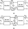 |
Figure 1 (a) Rectifier, (b) inverter topologies. |
The switching devices and magnetic modules of the DC-DC converter suffer larger losses as a result of the SHC. When employed with DC loads like Light-Emitting Diodes (LEDs), the SHC’s flashing light is damaging to the human eye [3, 4]. The SHC lowers the efficiency of energy conversion and reduces the longevity of DC sources such fuel cells and batteries [5, 6]. SHC must be decreased or eliminated in the DC-DC converter, the DC load, and the DC supply. Three main types of approaches are often used to lower SHC emissions. SHC is one of the most often used methods to avoid paying it since it preys on people’s innate passivity. Large electrolytic capacitors may be connected most simply in parallel with the DC bus [7, 8]. High-quality electrolytic capacitors, on the other hand, have a lifetime of just three to five thousand hours [9, 10] and it falls by 50% for every 10 °C rise in temperature [11, 12]. Electrolytic capacitors are the primary components that significantly shorten the service life of a single-phase converter. The second method [13] calls for connecting an L-C branch in parallel with the DC bus at a resonance frequency of either 2fin or 2fo. But because to the low resonance frequency, the L-C branch is comparatively big. The second strategy entails increasing the DC-bus port-impedance of the DC-DC converter (denoted Zbus(s) in Fig. 2) to 2fin or 2fo with the aid of an appropriate control scheme in order to force the SHC from the input or output of the downstream inverter into the intermediate DC bus capacitor and safeguard the DC-DC converter from contamination. To entirely reduce voltage ripple across the DC bus, a large DC bus capacitor is still needed. The third technique uses power decoupling circuits as a ripple power buffer and is based on the power decoupling idea. This may reduce the DC bus capacitance by removing the SHC in the DC-DC converter, the DC load, or the DC source. This implies that the electrolytic capacitor on the DC bus could be replaced with a more reliable film capacitor [14].
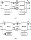 |
Figure 2 (a) BVCC (b) BCCC topologies. |
The SHC in mono inverters has been decreased as a result of thorough literature reviews from a variety of angles. The output impedance of a two-stage single-phase inverter’s buck-derived DC-DC converter serves as the foundation for an investigation of different control measures targeted at reducing SHC. Finally, a number of control techniques are used to assess the performance of the boost-derived DC-DC converter used in the two-stage single-phase inverter [15]. Only two-stage single-phase inverters are covered by [16] and [15] since the front-end DC-DC converter regulates the DC bus voltage. Power decoupling in solar micro-inverters without the use of electrolytic capacitors has been the subject of several investigations [17–19] examine several methods for power decoupling. The primary emphasis of [20, 21] is on active power decoupling topologies for single-phase systems. The impedance characteristics of the DC-bus port are disregarded in the two-stage single-phase converter. In actuality, the port-impedance characteristics of the DC-bus have a significant influence on the SHC reduction management strategy for various kinds of two-stage single-phase converters. For instance, if the front-end DC-DC converter regulates the DC bus voltage in a two-stage single-phase inverter, the control bandwidth must be purposefully lowered. However, if MPPT is carried out using the front-end DC-DC inverter design, there will be significant SHC in the PV panel, causing the operating point to deviate from the maximum pow. The SHC is distributed between the DC-DC converter and the DC bus capacitor due to the changing features of the DC-bus port-impedance, and this distribution may fluctuate dramatically even when the same management method is used. However, previous research have not been able to provide evidence to back up this claim. Because of this, it’s critical to assess how various two-stage single-phase converters vary in terms of the impedance characteristics of the DC-bus port. As a result, scholars have published a number of these models. This analysis of these models is in-depth for different use cases. We then carry out an empirical assessment of the models using a variety of qualitative characteristics in order to help readers choose the models that are best suitable for their needs. The last piece of this study contains some contextual comments on the examined models and some suggestions for enhancing their performance in real-world applications for various use cases.
1.1 Motivation of work
The motivation of this work is to solve the problem of diversity and time-consuming efforts in selecting the best controlling models for different configurations of converters. The converter systems like SEPIC and ZETA are bound to have vast differences in performance when they encounter differing load scenarios which leads to their ambiguity in application-specific deployment. This study addresses that problem by reviewing the literature models and establishing a new measure of assessing the ranking of different control systems of converters to enhance economy and efficiency in use of converters.
1.2 Literature review
Several researchers have put forth cutting-edge control techniques aimed at converters. Several biological inferences, neural networks and room learning have been mentioned here that improve conversion efficiency and adaptability of the model. This is, however, not the entire picture as difficulties still exist concerning the quality and quantity of assessment of such approaches. There were papers that confront the issues but they emphasized their attention on particular models rather than a general one upon which various models can be evaluated. In details we have mentioned more than 55 articles.
1.3 Study gaps
-
Lack of a standardized methodology for comparing the performance of diverse control models.
-
Limited exploration of the trade-offs between conversion efficiency, computational complexity, deployment cost, and scalability.
-
Absence of a unified metric to aid practitioners in selecting optimal control models for application-specific use cases.
1.4 Contribution
The present research work offers:
-
An in depth review of the alternative models of converter control, outlining their advantages and downsides from different perspectives.
-
An extensive account of comparison evaluation based on performance including conversion efficiency, operational deployment cost, delay, scalability and computational complexity.
-
The establishment of the rank metric namely the Converter Control Rank Metric (CCRM) which incorporates all the mentioned metrics for the purpose of selecting efficient, scalable and cost-efficient models suitable for use in realistic situations.
2 Detailed review of existing control methods
Different control models are used with DC-DC converters. Each type has distinct operating characteristics of its own. The researchers who participated in the study that was published in [22] highlighted that magnetic control of DC-DC converters is a significant advancement in the area of DC-DC converter control. These converters may be used to build LED drivers. The DC-DC converter’s performance while in discontinuous conduction mode is directly influenced by the Device’s Effective Inductance (DCM). Using a variable inductance, the converter’s output can be changed, allowing the amount of current going through the LEDs to be changed as well (VI). The research’s conclusions suggest that combining magnetic control together with LED loads might enhance the efficiency of DC-DC converters. In this instance, the duty cycle and switching frequency are both influenced by magnetic control. An experimental prototype was utilized to test the effectiveness of the analyses of the modeling approach and control technique.
Experts in regulatory systems have established that managing a management approach to regulate load voltage and distribute current is necessary when using parallel DC-DC converters [23]. This was shown by the need for the converters to be paralleled. The paralleling of the converters served additional support for this claim. The goal of this work is to defend control input channels against malicious data insertion attacks by providing a secure cooperative distributed control solution for parallel DC-DC converter voltage regulation and balanced current sharing. The use of cooperative distributed control will enable this. Using Lyapunov’s theory of stable networks and network management, researchers may swiftly demonstrate network stability. Applying the concept might be one approach to do this (LST). The developed cooperative distributed control technique may be resilient to minor DC-DC converter actuator damage, changes in load parameters, and changes in the converters’ physical characteristics. Each converter in the system may have a different control strategy from the ones used for the other converters, if desired. Extensive modeling and findings from the real world corroborate the method’s remarkable performance in balanced current sharing and voltage management in parallel converters, as well as its resistance to localized attacks such fraudulent data insertion. In-depth modeling greatly contributes to the approach’s exceptional performance in balanced current sharing and voltage management in parallel converters. Even more proof of the strategy’s resiliency in the face of these threats is the strategy’s enormous success.
The management of voltage and current in a series connection of DC-DC converters with various characteristics but the same ZIP demand has been studied [1]. Anytime the DC-DC converters are connected in parallel with one another, this problem arises. Therefore, it is necessary to create Distributed Dynamic Control (DDC). The total number of converters and the load profile are not at all taken into account in the proposed control system. Numerous subjects are discussed in the letter, such as load independence, scalability, and a stability analysis using Lyapunov’s equations. The setup has also been specified in addition to that. MATLAB/Simscape Electrical simulations of the case studies may be used to demonstrate the effectiveness of the control mechanism. According to converter designers, multilayer buck DC-DC converters provide low switching voltage stress, compact inductors, and a sizable power density [2]. Before the user can fully take use of the potential that the flying capacitor offers, the voltage must be stabilized. Buck It is possible for nonlinear and multilayer DC-DC converters to integrate a large number of inputs and outputs. Furthermore, there is no proof that they are in any sense proceeding in a linear manner. In order to manage voltages that are fundamentally interconnected to one another, the researchers created a decoupled optimum control technique employing inverse system theory. This was done in order to regulate the voltages (DOCS IST). The authors take use of an approach called inverse system modeling when creating a model for calculating the mean of a big signal. The solution to the challenge of selecting the linearization output function of the signal as the next stage in their analysis is then provided. Pseudolinear subsystems with a single input and output are created as a consequence of the decoupling and linearization of the system. The controller design process has been streamlined as a consequence of the linearized system being controlled by a large number of optimum controllers. Consequently, creating controllers has become simpler. In computer simulations using a six-level buck DC-DC converter for the assessment, the performance of the proposed control was better than a proportional integral control with linear decoupling. A three-level buck DC-DC converter prototype is utilized to gather experimental data. The approach is reviewed once the data have been gathered to make sure it is correct. Four different control strategies for DC-DC buck converters are designed, investigated, and analyzed by control system professionals in [3]. Control loops may occur in SAC, DA, and SDOB, to name a few. There are further instances (DDOB). Any potential issues brought on by the DC-DC buck converter are not taken into account when computing the nominal system for the SA and DA. The DA exercises control in a sliding and flexible manner, while the SA exercises control in a backtracking and shifting manner. Additionally, a technique is shown that may be used to generate SDOB and DDOB while taking into account the irrationality of the parametric variable values. On the other hand, DDOB utilizes a disturbance observer in addition to sliding mode control in order to perform its duties. A key component of SDOB is one’s ability to regulate backstepping. The four various types of control techniques that might be applied are the subject of experiments. Damage management experts did not agree with one another. In this article, I’ll demonstrate how to create a controller for a DC-DC converter with two inputs (DIDDC). The charge pump, buck and boost converters, and the converter itself are all located at the converter’s back. Here is a summary of some advantages that might be attained by using this topology: The load may be powered by one or both of the DC sources independently or simultaneously, and the existence of two control loops – one for controlling source current and the other for controlling load voltage – ensures efficient power transmission and management. The source current has very little ripple as a consequence of this design since both DC sources are connected by an inductor to produce a smooth source current waveform. A multivariable diagonal controller is in charge of controlling the input DC power within the framework of the closed-loop converter system. The first diagonal controller is in charge of controlling the load voltage, while the second diagonal controller is in charge of controlling the DC current from source 2. A converter with two distinct inputs and one output is an illustration of control-loop interaction. This kind of converter transmits electrical energy to the load from two separate sources. This is a result of the converter performing this function using comparable components. Decouplers are components that lessen the amount of contact between other components that are not diagonally aligned. The linear matrix inequality and the H robust control theory must be combined in order to create controllers that are trustworthy (LMI). A well-implemented LMI system may increase a controller’s capacity for organization and productivity (PID). By first developing a prototype for a topology that runs at 60/24 V to 48 V, 150 W, and 50 kHz, and then evaluating the parts of its power management system, the DIDDC’s multivariable controllers are put to the test. The demonstration follows this procedure. Some of the subjects that have been studied include current regulation, load sharing with input DC sources, source current regulation, load management, and load voltage control. The continuous, double-input, closed-loop converter technology can filter out a broad range of annoying noises.
Photovoltaic (PV) systems need elements like MPPT controllers and high step-up DC/DC converters in order to operate correctly, according to [5]. The results of this study suggest the use of a high-step-up DC/DC converter designed specifically with PV modules in mind. The main objective of largest power point tracking, also known as MPC-MPPT, is to locate the power point using as many sensors as is practical. The equipment that we provide you with has a 93% efficiency and a ten-fold improvement in input voltage capability since it was initially created. Photovoltaic (PV) systems often employ the MPC control approach because of its better steady-state and transient performance. There are many reasons why this is the case. It is crucial to employ not one, but two voltage sensors in addition to the current sensor in order to effectively monitor the power generated by solar cells using MPC-based MPPT. In order to reduce the system’s total costs, this study recommends employing a two-sensor MPC-based MPPT method. When the step sizes are altered to be variable rather than fixed, the performance of the approach is noticeably enhanced. The evaluation of the consequences of several different operating setups and conditions uses both Simulink and a physical setup. The simulations and testing are done to ensure that the analytical assessment the system provides is accurate. Applications that employ DC microgrids must have direct current to direct current converters in order to operate effectively, according to [6]. For the objective of increasing the effectiveness of boost converter overshoot suppression in the presence of load current and source voltage interruptions, we provide a unique low-frequency current-mode management approach in this study. This method’s specific goal is to increase the effectiveness of overshoot suppression [7]. The control approach employs both a dynamic current-loop controller with asymmetric saturation and a Proportional Integral (PI) voltage-loop controller (CDL). The fundamental goal of the dynamic current-loop controller is to improve reference current tracking while concurrently lowering low-frequency disturbances. The controller’s main job is to do this. The effectiveness of the approach is shown by the information gathered from the tests and simulation results combined.
The results of a research, modeling, and evaluation of a prototype DC-DC converter with four interspersed phases are shown in [7]. The concept is the joint creation of Cuk and SEPIC. The SIMO prototype is now being used. If you have access to and are able to use a DC voltage source, this combo converter enables you to produce two output voltages that are precisely the same. Multiphase interleaved DC-DC converters are superior than single-phase converters in terms of efficiency, dynamic responsiveness, and ripple. Better performance is achieved by multiphase interleaved DC-DC converters. Compared to single-phase converters, multiphase converters are better at controlling heat. Losses are spread out among a larger number of smaller components, which is why this is the case. As a result, a substantial quantity of power may be concentrated in a relatively tiny space. The study’s findings show that SOM and IOM are two of the best control strategies (IOM). Based on the simulation’s results, it can be concluded that the IOM has the capacity to stabilize variations in the current being input and output. Two examples of constructed proofs of concept are bipolar Direct Current (DC) powered microgrids (MG) and distributed power systems.
In order to manage fluctuations in the voltage that is provided by a DC microgrid, a control approach for an isolated DCDC dual active bridge converter is put forward in [8]. Changing the transformer’s output voltage while maintaining the same amount of average current flow across the transformer is not entirely impossible. The controller stores the linear representation of the GAM that makes up the system (SGAM). The data obtained from the simulations and experiments are used to examine the hypothesis.
According to control system researchers [9], the use of DC-DC converter systems has increased across a number of industries, including both the military and the private sector. This paper presents a novel digital FTSMC method for dealing with mismatched disturbances in DC-DC buck converters. We initially use Euler’s discretization method to get data that is as close to the real data as is realistically practicable before continuing on to analyze the discrete-time model of the converters. It is difficult to locate the oscillations produced by clustering when using delayed estimate. By adding disturbance compensations to a modified digital fast terminal sliding mode surface, a suggested controller is created. Through modeling and testing in the real world, the feasibility and applicability of the digital FTSMC technology are demonstrated, proving its efficacy. Along with the dynamic capabilities of FTSMC technology, voltage tracking accuracy has increased, and this is true across a wide range of operating circumstances.
A multiport automotive-grade magnetically coupled DC-DC converter with nonlinear control is shown in the schematic [10]. It is shown that this converter is in use. To create a model of the system’s dynamic behavior, the researchers utilized an average of the port’s power. After that, you should focus mostly on developing a system for feedback linearization control. Even in the presence of changing control and state variables, conventional PI models nevertheless maintain asymptotic stability and load uncertainty resilience (US LUR). Performance is hampered and suffers as a consequence when nonlinear control changes are used instead of linear approximations. The control mechanism’s simple and effective design makes the most use of the available area. The knowledge gained from the research was useful to the controller.
To gain the best control of the servo and regulatory responses of a boost-type DC-DC converter operating in continuous conduction mode, a voltage-mode management approach with two degrees of freedom is required [11]. When using model-based digital controllers like MDC and Vogel-Edgar, it is possible that servo behavior may alter (VEC). VEC motors and motor-driven fans are certainly necessary to avoid input overheating during transient voltage periods (MDC). In order to improve the regulatory system’s responsiveness, we are creating a dependable internal-loop compensator that is based on a model. This is accomplished without needing any modifications to the structural components of the VEC or MDC (RIC). Any disturbances will not be taken into account by the feedback controller if they have not been measured by this RIC first. This is so that the feedback controller may only respond after measuring the disturbances. Modeling studies and experimental verifications were used to assess the performance of the proposed integrated control system in both servo and regulatory contexts. The simulation results, assuming appropriate tuning settings for the RIC, show that the recommended strategy enhances the regulatory behavior of the VEC and MDC without degrading the servo behavior of any component. This is predicated on the notion that the RIC’s tuning settings are precise. The responses of simulated closed-loop systems and those of experimental ones must have a high degree of concordance in studies that assess the accuracy of simulations.
Solar Photovoltaic (PV) systems will always need batteries and other Energy Storage System (ESS) components to provide a constant supply of power. The best choice, according to reference [12], is a DC-DC Flyback Converter that uses Active Clamping (FCAC). The author of this article suggests using a Multiport DC-AC Converter (MPC) with differential power processing for solar systems that are powered by batteries (DPPC). Even when all three energy sources (AC grid, batteries, and solar panels) are contributing, the MPC is in charge of managing the energy that the DC-DC converter is unable to regulate. If the suggested structure is effectively applied, the end result ought to be enhanced integration, which ought to lead to increased output and decreased expenses. The innovative cooperative control system that combines MPC and DPPC is powered by a variable active power flow. The MPC uses space vector pulse width modulation to account for voltage changes [13] brought on by both the battery and the PV. Both the power rating of the DPPC and the active power control of the MPC are subjected to quantitative investigation. For an experiment to be completed successfully, control, setup, and modulation methods are crucial. The study cited in [14] presents a control design approach, which has the potential to be extended to more recent high-order dynamic DC-DC topologies. This article compares and contrasts model-based controller design with model-free controller design. A model-based approach might still work with just a few sensors, even for converters with several parts (such as multilevel, quadratic, input/output LC filter-based converters, and so forth). Models are mathematical representations of the actual world, which explains this. The computation of the system’s state variables is not necessary since gain modulation employs Time-Response Parameters (TRP). This method is thus more effective. Each and every one of these characteristics, as well as a multitude of others, are present in model-free control. For instance, gain adjustments are possible when controllers are built using measurement data. Discrete time allows for the digital tracking of controllers, which is crucial for certain games, and makes this possible. Both of these phenomena are also feasible in discrete time. In order to evaluate the many proposals, a sixth-order closed-loop control system is used.
Two advantages of high-frequency digitally controlled DC-DC switching converters are their high-power density and their rapid transient response. [16]. The authors describe high-frequency DC-DC switching converters in connection to a digital current-mode controller, abbreviated as DCM. This controller’s output features an inductor in addition to a voltage and current compensator. The voltage compensator is used instead of the shift operator when the delta operator is required since it is a more suitable component. This modification has the potential to lower the cost of the underlying technology while simultaneously improving the control precision. When an Advanced Sampling Predictive (ASP) control mechanism is used, both the processing demands placed on the compensator hardware and the costs associated with those demands are decreased. Additionally, it reduces the noise that is made when the power switch is turned on and off. By using an FPGA-based design and a switching frequency of 2 MHz, we are able to build buck DC-DC switching converters. Numerous studies have shown that the delta operator may improve control precision while also lowering the cost of the underlying technology. The highly recommended digital current-mode controller performs better than a single digital voltage compensator when it comes to handling transients. When applied to high-frequency digitally controlled DC-DC converters, the suggested control strategy and algorithm provide performance that is really extraordinary.
The personal computer’s flexible control system offers the chance to improve performance while adhering to established current and voltage constraints [15]. It cannot be employed in any capacity in power electronics because to the significant processing that would be necessary. The whole control activity may be finished in less than 30 microseconds by using the learnt controller of a reasonably priced 80 MHz microcontroller. The speed of the microcontroller makes this possible. A variety of designers have offered model-based enhancements to enhance the full-bridge (FB) DC-DC converter’s dynamic performance [17]. The duty ratio, as well as the converter’s input and output voltages, are disregarded by both the controller and the technique for managing a single voltage loop. Additionally, the load resistor is not at all taken into account in this analysis. The amount of fuzzy-adjustment that is made to the output voltage in response to disturbances has a direct impact on how well the dynamic system works. The objective of this work is to design a precise technique for modulating the current sent, beginning with the capabilities of FB DC-DC converters. The approach will be designed to do this. This basic DCC method employs the load current and input voltage as feedback, resulting in a rapid and responsive dynamic response. The performance of the control system may be adversely affected by power losses and control latency, among other possible variables. In this case unknowables affect the method’s dynamic performance, a remedy is offered here. Since the proposed DCC approach with compensating operation includes circuit elements like the output capacitor and leakage inductance, incorrect circuit parameters may have an impact on performance. It is vital to estimate these two circuit properties in order to ensure that the DC-DC converter will operate dynamically. Modeling and testing have shown the dependability and value of DCC.
According to industry professionals [18] in the area of control systems, the Class E DC-DC converter is the best option for high-frequency applications. This conclusion may be drawn as a result of the converter’s simple zero-voltage switching mechanism. In order to handle a wider power range, this research project aims to improve the hysteresis control of a Class E DC-DC converter (MPLs). In order to pick the two input power levels that are closest to one another, choose the two input power levels that are closest to one another in analogy. A larger range of input power levels is possible because to the MPL hysteresis control’s reduced modulation frequency and mode transition losses as compared to the on-off control. The wide variety of input power levels is also handled by the MPL hysteresis control. Conduction losses are being reduced as a result of this increases the converter’s ability to perform its tasks successfully. The following is a list of the specifications for Class E DC-DC converters that employ MPL hysteresis control, including switching frequencies. In conclusion, the creation of a 10-W Class E DC-DC converter prototype and subsequent testing allowed for the successful demonstration of the MPL hysteresis control mechanism. It may be helpful in a variety of situations to have an input voltage that can vary from 9 to 18 V.
The study cited in the reference [19] investigates the subject from the perspective of a control system designer. There are many positive characteristics that these converters provide may be partly to blame for the great adoption of DAB DC-DC converters. It could be easier to manage input voltage and load variations by improving the dynamic performance of the DAB. Modern systems may be created either sequentially or concurrently, depending on how the model-based components are connected to the compensatory ones. The parallel control architecture that allows compensatory and model-based control approaches contains both of them. Series control systems’ compensation is calculated by multiplying the system’s component values by a model-specific factor and adding the result. Both control techniques have the ability to provide good dynamic performance for DAB DC-DC converters when feedback management is correctly carried out. Having said that, this is only true if the right techniques are used. The fast-dynamic control system and its possible application to parallel and series structures are both examined and further investigated in the course of this study. The researchers develop other strategies after analyzing both sets of processes and taking into account each one’s benefits and drawbacks. A DC-DC converter that uses a DAB implements model-based control as opposed to the more typical PI parameter design. In this study, we investigate the control delays of the two proposed systems and provide a useful real-time approach for addressing these delays. The next paragraphs contain our results.
Multilayer DC-DC converters have the ability to do both, reducing voltage and current shocks while increasing capacity [20]. The difficulty of managing the voltage and the current is substantially enhanced when the proper values for the parameters are not entered. This research studies the application of incremental passivity control as a technique for current distribution across the layers of multilayer DC-DC converters. The use of FTE PC might increase a company’s resistance to demand changes. The recommended approach yields a control rule that is both linear and bilinear. The results of certain research indicate that changing an inductor’s settings has little effect on the device’s ability to distribute current or maintain stability. The closed-loop system’s ability to handle both linear and nonlinear loads is shown by the length of time it has been in operation. The next stage will be to simulate the suggested control system so that we can evaluate both its resilience to disruptions and its sensitivity to changes in the external environment.
Separated Dual-Active Bridge (DAB) DC-DC converters may benefit from Cooperative Triple-Phase-Shifted (CTPS) modulation [21]. The CTPS-controlled DAB converter’s mathematical model and closed-loop control architecture are both closely held trade secrets. Neither has been made known to the public. Here is the first demonstration of a CTPS-driven DAB converter simulation using an average state space representation. As a zero-order system, the CTPS-driven DAB converter lacks a current closed-loop control loop for the inner inductor. This is so because the DAB converter is being driven by the CTPS. provides a visual picture of the energy production process. One adjustment may be made to the output voltage, and the other to the transfer power, using the DAB converter. In terms of the control systems used, it matters whether the DAB converter is connected to a resistive load or a DC microgrid. The power averaged through time model has a wide range of applications. It was crucial to utilize the data gained from trials to confirm the accuracy of the mathematical model and the closed-loop control systems. More proof for this argument can be found in [24], which shows the V2 switching converter control’s rapid transient response [24]. The digital V2 controller IC considerably enhances the DC-DC converters’ transient responsiveness. Along with PID and PC compensators, the controller’s IC also has PWM, ADC, and other components (DPWM). The PID compensator replaces the shift operator with a delta operator to save overall hardware costs while improving converter stability. The compensator will average it out and smooth it out, making the predictive control more sensitive. The employment of a differential bias circuit in combination with an ADC that has a 6-b delay-line window is one method of increasing the linearity of an ADC. Both linearity and die area are consistently maintained while employing 11-b hybrid DPWMs. In addition to the DLL, this package also contains the counter and the segmented delay line (DLL). A CMOS digital V2 controller IC prototype made using 180-nm technology was created to test buck DC-DC switching converters. Everyone who took part in the experiment experienced a brief period of stuntedness. The National Institute of Standards and Technology recently released the findings of a research that looked at how climate change impacts the development of technology (NIST). The auxiliary converters employ cascading chopper cells, while tiny inductors control the current flow in the main converters (CCC). No of the load or the high-to-low voltage ratio, DC-DC converters’ [25] ability to execute Zero-Current Switching, commonly known as ZCS, does not alter. It is exceedingly improbable that either side of the converter will still contain square-wave currents once the effect has completely been realized as a result of this. This article’s goal is to demonstrate a variety of control strategies and operational concepts using a simple model with 200 V and 2 kW of power.
A continuous-conduction PWM DC-DC buck converter should be utilized with a nonlinear voltage-mode controller, per reference [26]. It is advised to use this set up. It is advised to use this combo. The control procedure may be simplified by combining averaged DC-DC buck converter dynamics with Sliding-Mode Dynamic Control (SMDC). Instead of using capacitor current, the feedback loop of the proposed control method uses output voltage. As a result, the cost of incorporating analog signals will be decreased, and the usage of an expensive current sensor will be unnecessary. A simple analog circuit composed of a few operational amplifiers (op-amps) and resistors could be able to address the control issue. The availability of detail is aided by both modeling and building controls, which are both significant factors. Because of this, both the environment and how people live continue to be unaltered. We have been modeling and simulating the controller’s behavior in MATLAB and SaberRD as part of our inquiry into it. A voltage-mode controlled buck converter prototype is also currently being constructed. It seems that the controller maintains its tracking capabilities while keeping the switching frequency constant based on the modeling and testing findings. It is highly advised to use DC-DC converters made by DAB-LLC-DCX for applications that use point-of-load [27]. Given that this converter uses ZVS for every switch and ZCS for the rectifier, it may be able to provide the maximum degree of voltage control. For a high level of efficiency and reliability, the suggested converter must support ZVS operation over the whole board, for all switches, and across the full power range. Directly as a result of this, the microprocessor may operate more effectively while experiencing less strain. If the converter is controlled via hybrid control, the switches in the suggested converter will be able to regulate ZVS operation across their whole power range. The ZVS has substantially increased its capacity for productive work by skillfully regulating phase shift while working at high input voltage. Variable gain LLC converters may be able to force DAB converters into ZVS mode while running at low voltage. To make sure that the same proportionate quantities of charging and discharging occur, ZVS inspects the connections of the capacitors. It not only describes the idea, but also the structure and constraints of the system. The 80-W prototype was examined, and it became clear that the predicted paradigm was correct.
The inventors of the concept claim that the need for buck-boost converters, which may be utilized in DC microgrids, has significantly increased as a result of recent developments in power plants and other sources of energy (MGs) [28]. The varying power requirements of the applications might make these connections difficult for MG applications (CPLs). Researchers are compelled to create their own technique for preserving voltage stability in DC-DC converters in order to power low-ripple applications that need continuous power since there is so little information about DC MG systems. This is a result of the dearth of knowledge about DC MG systems (CPLs). Deep reinforcement learning (DRL) and actor-critical design may be used to stabilize CPLs even if the reference voltage varies. If the feedback controller gains of the ULM controller are read as altering controller coefficients, it is conceivable to combine online neural network learning with DRL to produce adaptive controller coefficients. Gains are a component of the controller that may be programmed and changed (NNs). The gains of the ULM controller may be dynamically changed to prevent the power electronic system from becoming unstable. In order to establish whether or not the suggested adaptive technique can really be executed, the results of a DC-DC converter that were acquired by a dSPACE MicroLabBox CPL real-time testbed are examined. Power electronic transformers must have high-frequency bidirectional dual-bridge series-resonant DC-DC converters. It is impossible to exaggerate the significance of PET converters [29]. The authors of this research suggest utilizing a predictive power management technique based on a phase shift modulation model to improve the dynamic responsiveness and durability of the converter (MPC PSM). The given technology has the potential to provide extraordinary dynamic properties since the operating point is independent of the converter’s resonant parameters. It has this potential even if it is not the most effective way. The efficacy of the proposed control is shown using a load sample made up of an inverter and a 400-W resistance. In comparison to conventional voltage loop control and model predictive voltage control, the proposed technique could be able to provide a faster dynamic output voltage response to load and input voltage step changes. Both of these methods of exercising control have been created in the past. One of the aspects of the Model Predictive Control (MPC) method is indicated in the reference [30] as auto-tuning of the MPC approach for the weighting components. One of the hallmarks of the MPC approach is this. The standard MPC must be updated since the operational environment of the converter is always changing. Therefore, this is something that must be accomplished. Once installed, the controller will no longer work as intended due to the upgrade. The weighting factor limits the switching frequency of a DC-to-DC converter to a certain range. The ripple in the inductor current and the switching frequency may be used to connect an MPC and an autotuning weighting factor. The weighting may cause the switching frequency to fluctuate at various periods. The weighting factor cannot be adjusted in order to retain compliance with the requisite MPC, even if the converter’s operating point is altered. A test of the suggested control mechanism’s performance is possible by changing the input voltage, load, and other elements. Examining the variations in outcomes between the earlier MPCs and the most current ones. Even if the operating mode is changed, MPC may still change the switching frequency in order to satisfy its requirements. In real-time applications, inconsistencies in parameter values should be actively looked for in accordance with MPC algorithms and other more contemporary approaches [31–35].
The concept of stabilizing continuous-power DC-DC converters is covered in a study by control system designers that was published [36] (CPLs). A boost converter is a component that is used by EMPC. Find a solution to the multiparametric and efficient nonlinear programming problem over the simplex state space division. You may then choose which control rule is the most efficient using this information. The method of performance assessment may include both in-person and online testing, or just one alone. Any outage that happens while a deployment is taking place online might incur costs. Regardless of the changes brought on by the CPLs, the regulator is in charge of raising the output voltage and maintaining the stability of the system. It ensures correct operation throughout the whole process, despite unanticipated changes in the load or the input voltage. Research on the SIMO buck/boost DC-DC converter with mean control was presented, published, and referenced [37]. The duty-cycle and control-current predictors allow for accurate and timely monitoring of the inductor reference current. Cross-regulation on the last channel may be achieved by utilizing a duty-generating circuit based on Autotuning Dividers (ADDC). It is advised to operate the system in boost mode and use an anti-right half-plane zero strategy in order to avoid cross-regulation during high loading transients. The recently created SIMO buck/boost DC-DC converter uses CMOS technology and has a 0.35 nm feature size. The converter also has four boost/buck output channels. When placed through a loading transient of 300 mA on a boost channel, the highly suggested DC-DC converter has a cross-regulation of less than 0.05 V/A, a load transient reaction time of less than 40 s, and a peak efficiency of more than 89%. Furthermore, it responds to load transients in less than 40 s. Its load transient response time is also much less than 40 s.
According to the work that was described in [38], in situations when input current measurement was not available and load was unknown, researchers developed an adaptive DC-DC boost converter control by using a model-based approach. The adaptive observer design has the potential to generate a broad range of distinct equilibria, which may be troublesome given the unpredictable nature of the output dynamics. Before a system can even start to converge on a solution, it must first overcome the detectability barrier. Saturated dynamic controllers, or SDCs for short, are the elements in charge of controlling the asymptotic output voltage. Even when continuous stimulation is no longer required, convergent behavior may still be maintained by the controller and the adaptive observer thanks to immersion and invariance. In order to directly compare the transient behavior of the proposed controller with that of two alternative output feedback controllers already in use, we employ simulations. It is absolutely possible to verify the outcomes of theoretical research and computer simulations using a functional DC-DC boost converter prototype. Reference [39] asserts that in order to improve the performance of DC-DC power converters in unexpected dynamic conditions, converter designers are tasked with creating and testing a Frequency-domain Robust Controller (FRC) [40]. This method directly increases the dependability of the converters. There is no assurance that this control system will be able to appropriately moderate input voltage changes and load fluctuations. These unknowns allow for the restriction of the phase margin and/or gain margin, which will provide predictable performance and steady system operation. Currently, the suggested corporate control technique is being looked at. This may be similar to a few different control methods that are used today. The theoretical assumptions are verified using a test board particularly made for buck converter systems [41–45].
These models also showcase lower delay but can be used large-scale scenarios. Thus, these models must be used by control system designers to develop high-efficiency converter control circuits.
A DC-DC power converter is necessary to handle a stiff DC bus and provide power to the load, according to control systems specialists [40]. This was established as a consequence of the FC stack’s nonlinear Volt-Ampere properties. This has been shown to be true. With FC applications in particular mind, a dependable controller for a DC-DC interleaved boost converter was designed (ESO). We’ll also be concentrating a lot of attention on the PI controller in this project. When the PI control rule is reformulated as a unified kind of disturbance observer-based control, it is shown that integral action is the most accurate technique for estimating disturbances. This section will begin with an examination of the performance of these two controllers in a hypothetical scenario. The proposed controller outperforms the PI controller and does not need any additional sensors. The proposed controller outperforms the alternatives in both the simulation and testing stages.
Parallel DC-DC converters are used in several applications, such as computational power supply, DC microgrids, and point-of-load systems [46]. Ripple cancellation and switch interleaving are two techniques that may be employed in communication networks with a considerable number of converters. The vast majority of systems need a converter in addition to a centralized controller to effectively handle ripple. This is due to the possibility that ripple may interfere with the transmission. As a direct consequence of these strategies, the system’s scalability and dependability are both compromised. Only homogeneous setups can be managed by decentralized systems; converters with a broad range of operating points or characteristics cannot be managed by them. By incorporating PWM HC carriers into phase adjustments that lower ripple, this approach gets past these restrictions and mitigates their effects. The quantity of apparent switching harmonic that is present in the output current and voltage may be decreased by the controller, which comes with a very strong suggestion. This is achievable because local voltage feedback is used. Applying the strategy to a system made up of five parallel-connected buck converters with incompatible operational and parameter settings serves to verify the method. More than four decibels (dB) can be taken off the output voltage’s ripple, and more than 30 dB can be taken off the fundamental switching frequency harmonic (dB). If they flip at a certain frequency, a buck circuit could be able to control the input voltage of these converters. In this work, the following types of pulse-width modulation were examined and contrasted: conventional pulse-width modulation, conventional shifted pulse-width modulation, hybrid shifted pulse-width modulation, enhanced shifted pulse-width modulation, and asymmetrical pulse-width modulation [47]. The design of a series-resonant DC-DC converter with a voltage doubler rectifier acting as a step-up component is well suited to this research on integrating renewable energy sources into DC microgrids. Analytical investigations on voltage buck control strategies were possible because of the potential power losses (VBCM). It was required to compare theoretical and real data in order to verify the calculations and assess the effectiveness of several voltage buck control procedures. The two separate sets of data may therefore be compared thanks to this. An experimental 250 W hybrid PSM demonstrated its efficacy. The findings of the evaluation of analytical and experimental estimates of power loss revealed that there was often no difference between the two forms of calculations.
Two weight resistors are required to build a multiloop Constant On-Time (COT) controlled buck converter [48]. As a result, it is feasible to monitor both the output voltage and the inductor current. By including a Proportional-Integral (PI) compensatory gain in the outer voltage loop, an unstable state is created when the output capacitor has a low equivalent series resistance. This kind of gain might be present in the circuit (ESR). As a consequence, the effects of the stable circumstances of the inner and outer voltage loops have been disregarded. You will need a piecewise linear model driven by a multiloop COT-controlled buck converter to overcome these challenges. To demonstrate that the system can be trusted, an analysis of the dynamical distributions of the control weights and circuit parameters is conducted. Additionally, stability constraints are set up so that it is possible to distinguish between operational parameter values that are unstable routinely and those that are unstable abnormally. This goal is accomplished by contrasting typical unstable values with atypical unstable values. A discrete model will be necessary to satisfy a special criterion for control weight stability in order to account for this divergence. examination of the activity pattern that the control weight displayed during the transitioning stage. The measurements obtained from the PSIM simulations and the hardware circuits both support the idea. The purpose of this article is to reduce the amount of excessive short-circuit current by introducing a novel design approach for a DC-DC converter [49–54].
Convertor-Designers conducted the research that served as the basis for this essay, and it was initially presented in [55]. The use of a novel half-bridge design with two windings reduced the amount of the LV short-circuit current to a level that was more controllable. The high-voltage side of the converter is built using a hybrid bridge. To increase the efficiency of hybrid-bridge converters over a broad range of input voltages, the control is advised to include five distinct levels. The converters will be able to manage the input voltages more successfully as a result. It’s possible that the control strategy that was shown is to responsible for increases in reactive power, current stress, and Zero-Voltage Switching (ZVS). A Proportional-Integral (PI) regulator and a single control variable are all that are required to implement this power management system. Testing and modeling both show that the control seems to function more effectively in actual situations than it did in the fictitious ones [56]. AC-DC converters may now receive direct power transmission from low-voltage energy storage systems thanks to the development of a grid-connected Quasi-Single-Stage Converter (QSSC) (LV ESS). The abbreviation “QSSC” refers for “Quasi-Single-Stage Converter”. The voltage vectors on the AC side of the QSSC are not distributed equally as a result of this. The cause of this is that the amount of charge that is present within the ESS affects how much of the DC-link voltage that is present between the two ports of the QSSC changes. Control and correction issues are unique to the nonlinear AC-DC conversion that QSSC performs. Using model predictive power management and treating the two ports as if they were a single DC source, this article proposes the idea of a virtual two-level converter that regulates the amount of power delivered to the grid. By doing this, the author is able to control how much power is sent (MPPC). To decrease the amount of power required by the DC-DC converter, the switching pair duty cycle may be changed. For a two-level converter, the monitoring errors are taken into account while calculating the duty cycle. There are various different sorts of errors that might occur while measuring both active and reactive power. It is hoped that by doing away with the difficult MPPC implementation of a three-level converter, it would be possible to develop a QSSC controller architecture that is easier to understand. Using experimental data sets, the MPPC technology and the concept of a virtual two-level converter have both been validated for different use cases [57, 58].
MIMO DC-DC converters may combine combinations of input source load and output load, according to the information in reference [59]. This article recommends adopting a high-ratio single-inductor MIMO DC-DC converter since it is reliable and efficient. The converter that is suggested eliminates the risk of cross-regulation and makes adding and removing input sources extremely straightforward. It’s feasible that each output has a distinct control of its own that can be separately updated. This would stop any additional outputs connected to the device from being affected by a change in load. Make sure you’re always adhering to the most current and relevant laws. When a constant current is simultaneously flowing through all of the input cells, the power generated by each source is precisely proportional to the voltage of that source. Because they can provide a preset quantity of power by adjusting their on/off phases, direct Duty-Cycle Controlled Input Cells, sometimes referred to as DCC ICs, are perfect for use in the management of continuous current in certain applications. They are thus a fantastic option for managing continuous current in such applications. Additionally, the results are unaffected by the sequence in which the switches are switched. This directly affects the design choices for free-form I/O expansion and may simplify them. A prototype with two inputs and two outputs is now being created to test if the converter can be technically accomplished. This schematic is an example of a subassembly diagram. Experts in control system design have devised a novel method to prevent the input voltage balance in dual-active-bridge input-series-output-parallel DC-DC converters from being imbalanced [60]. This method was created to stop input voltages that were not balanced. By using this technique, direct current will switch from flowing in series to parallel and will flow in the opposite direction. The suggested method lowers coupling between the Input Voltage Sharing Regulators (IVSR) and the output voltage regulators while preserving the uniformity of the input voltage distribution across all of the modules (OVR). The study’s findings indicate that conventional control techniques are insufficient for decoupling IVSRs and OVRs [61]. The development of control structures that can decouple from one another was significantly accelerated by offering an intermediate control variable that can be changed using IVSR and OVR. As a result, the procedure moved forward considerably more swiftly. Additionally, they made very precise estimates of phase-shift ratios. To decouple the control system in a proper way, one must implement entirely novel control principles and a language. Up until this point, much research had been done on both the transfer functions and the technique’s overall architecture. The distinction between IVSR controllers and OVR controllers has been abolished as a result of the creation of this new control technology. By comparing the outcomes of the experiment and simulation, it was feasible to illustrate the value of the creative control approach. This was a strategy that was up for discussion.
The linear-quadratic regulator was developed by modelers in [61] to enhance the closed-loop control of Dual-Active-Bridge (DAB) converters (LQR). Its foundation is based on an inequality in a linear matrix. The DAB converters’ output voltage was thus more consistent as a consequence (LMIs). By using a basic DAB comparator circuit, the audience is first shown an example of an inefficient DAB converter. They are then shown using the intricate DAB conversion device. LMIs are used in enhanced LQR control to identify the best control parameters that are consistent with the set restrictions. The dynamic performance of the system has been enhanced by updating the LMI-LQR hybrid closed-loop control and increasing the output current. Regarding load and line interruptions, comparisons are made between the traditional load quality ratings and the LMI-performance load quality ratings proposed in this research. Both conception and actual world testing have been used to demonstrate the suitability of the proposed regulations.
The creators of DC-DC converters allegedly created a unique nonlinear control mechanism for continuous-conduction-mode converters, and constant electrical consumption exacerbates the instability, according to the research’s authors [62]. One of the assertions in the research is this. Additionally, the study’s authors contend that the instability is exacerbated by the usage of DC-DC converters in continuous-conduction-mode converters. The conceptual framework that was provided was based on measurable, nonlinear voltage and current fluctuations that could be seen. Unlike current/voltage coordinates, lifted models (LM) have the potential to have their stability imposed by the control architecture. The current/voltage coordinates are the opposite. The current and voltage coordinates are different from this. Three entirely different nonlinear stabilizing controllers are provided by the authors to demonstrate the flexibility of their approach. The various controllers exploit the lifted dynamics in a number of different ways. To provide closed-loop stability and power sharing in a DC microgrid, control system experts created a current-limiting droop controller for paralleled DC-DC boost converters with constant impedance Z, constant current I, or constant power P loads [63]. With loads that have a constant impedance Z, constant current I, or constant power P, this controller is intended to operate. When used with P loads of constant power, this controller performs well. This controller ensures that each converter has built-in current-limiting, regardless of the kind of load or the magnitude of any changes in the load, by monitoring the output of each converter (NCLC). The load was then kept at Z, I, or P while an analytical test of the DC microgrid system’s closed-loop stability was run. The suggested controller provides perfect power distribution, constant voltage regulation, efficient closed-loop operation, and a current limiter for all Z, I, and P loads. The parallelization of several boost converters results in the emergence of nonlinear dynamics. The results of modeling and experimentation are compared for two parallel-operated DC-DC boost converters with a P load. To further understand the stability of the system, a performance analysis of the proposed controller will be conducted as part of this comparison.
A novel method of regulating a dual active bridge series resonant converter is presented in paragraph [64], which is located here. You can find this technique here. The technique enhances the converter’s immediate responsiveness without affecting its long-term stability. These characteristics make the converter potentially useful in novel circumstances that need high dynamics but are beyond the purview of existing feedback systems. These techniques are unable to handle typical combinations. Within the framework of this research, the authors provide a nonlinear control method based on Lyapunov’s theory for the generalized averaged converter model (LT). Before the method is encoded into a microcontroller or digital signal processor, it is adjusted using sensor-free techniques to make up for missing data on certain variables or adaptive control rules to take into account unknown model parameters. Before the technique is actually used, several changes are made. This update takes place prior to the method being saved in any of those devices, therefore it has no impact. The method will be stored as a file that may be performed once it is complete. By substituting a commercial converter for the standard technique and comparing the results with those of other alternative control methods, we were able to draw these findings [65]. The regulators created a controller that is responsive and inventive in order to manage the island DC Microgrids (DCMGs) that are used in marine power networks (SPSs). The DCMG is in charge of controlling the voltage on the island for both the CPLs and all of the SPS propulsion demands. The DCMG’s distinctive nonlinear droop control allows the ship’s principal control level to respond quickly, regulate voltage accurately, and distribute current sensibly. The voltage oscillation and the distribution of the current will both improve if the strategy that has been explained is used. A high-bandwidth Fractional Order General Type-2 Fuzzy Logic Proportional-Integral-Derivative (FOGT2FPID) controller is used within the context of the DCA-based method. As a result, it is able to quickly and accurately modify the DCMG voltage. It may be possible to do a Hardware-in-the-Loop (HiL) demonstration to showcase the novel technology.
NMP converters, sometimes referred to as non-minimum phase DC-DC boost converters, are intrinsically unstable [66]. The converter’s way of controlling voltage is to blame for this instability. A trustworthy Proportional Integral Derivative (PID) controller is built utilizing a condensed version of the quantitative feedback theory, which uses the output voltage sensing as feedback. The concept was created by QFT. This action is being made right now to address and eventually resolve the instability problem. There are several advantages to the PID system that is based on quantum field theory, some of which are as follows: The output voltage disturbance rejection is improved, current measurement is avoided, it is feasible to design the non-minimum phase directly, and disturbance dynamics (variations in input voltage and load current) are taken into account during the design stage. The PID controller that has been proposed works quite well in both simulated and real testing, outperforming the preceding method in terms of performance.
A modified FTSM that operates at a switching frequency that has been predetermined is often used in DC-DC buck converters [67]. The suggested FTSM’s many potential sliding surface and switching control system options are looked into, and each one’s availability, robustness, and stability are examined and assessed. A frequency control loop is necessary for a FTSMC to keep switching frequencies steady. This occurs as a result of the fluctuating switching frequency. The single voltage sensor provided still another suggestion, that of using a fixed-frequency FTSM. The control approach that is so widely used offers a number of advantages that are unique to itself, including an immediate dynamic response, a constant switching frequency, and an easy-to-navigate controller architecture. Numerous tests have been done to determine how accurate the suggested control mechanisms are. Both steady-state and dynamic transients, which are changes in the load resistance, input voltage, and reference voltage, respectively, may be handled by the approaches that are now being used. research, analyze, and assess the proposed strategy while comparing it with four conventional strategies.
A rise in the usage of renewable energies with energy storage in electric automobiles, electric boats, and smart grids was noted by control systems experts in [68]. Additionally, the United States saw same tendency. This most recent trend could be attributed to the increase in demand for electric vehicles. Power systems’ ability to use the many energy sources at their disposal in the most effective ways is restricted in the lack of a steady controller, which lowers their overall efficiency. It is possible to employ LPV as a management approach for an EB’s energy resources. Fuel cells producing 5 kW of electricity, the Sun producing 5 kW of electricity, and energy storage producing 2 kW of electricity. The LPV manufacturing method incorporates sector nonlinearity to enhance the dynamics of each component. After that, the duty of calculating the profits that each state has made is applied via the LPV control mechanism. When energy resource pulses are utilized as a power source, boost converters are in charge of controlling the DC-link voltage and providing electricity to EB loads. When energy resource pulses are employed as a power source, this is the situation. The suggested control approach maintains the system in a stable condition so that it may be utilized. It does this by taking into account the dynamics of each design element. This makes it possible to use the system. An aggregate set of constant DC-link voltage levels may be maintained by the newly designed controller, according to studies employing real-time simulations. As a result, every converter control type has a different set of internal operating characteristics. The next section of this paper compares these characteristics, enabling readers to choose optimal models for their particular performance requirements.
3 Result analysis and comparison
Based on the extensive evaluation of different control models, it can be observed that these models vary widely in terms of their performance characteristics. Thus, this section compares these models in terms of their Conversion Efficiency (CE), cost of deployment (C), delay needed for control (D), scalability (S) and Computational Complexity (CC) for different scenarios. These metrics were evaluated by quantifying them in terms of Low Quantization Value (LVQ = 1), Medium Quantization Value (MVQ = 2), High Quantization Value (HVQ = 3), Very High Quantization Value (VHVQ = 1), which will assist readers to compare them on uniform scales. This comparison can be observed from Table 1.
Comparative evaluation of different control techniques.
Based on this comparison, it can be observed that Fuzzy DCC [17], FTE PC [20], PI ESO [40], and PWM HC [46] is able to achieve low cost of deployment, while PI CDL [6], Fuzzy DCC [17], PI ESO [40], and FOG T2F PID [65] have lower computational complexity, thus can be deployed for cost-aware and simplistic use cases.
While, MPC MPPT [5], RIC [11], Fuzzy DCC [17], DRL [28], NMPC [30], PI ESO [40], COT [48], DCC IC [59], and QFT [66] have higher conversion efficiency, and DRL [28], PI ESO [40], and FOG T2F PID [65] have lower computational delays, thus can be used for high-performance and high-speed deployments.
Models proposed in IOM [7], MPC DPPC [13], PI DAB [19], DRL [28], PI ESO [40], and FOG T2F PID [65] are highly scalable, thus can be deployed for large-scale applications. To further simplify model selection process, a novel Converter Control Rank Metric (CCRM) is evaluated via equation (1), (1)
(1)
As per the evaluation of this metric, and Figure 3, it can be observed that PI ESO [40], Fuzzy DCC [17], FOG T2F PID [65], DRL [28], FTE PC [20], and PWM HC [46] are capable of achieving lower cost, with lower complexity, and higher conversion efficiency levels.
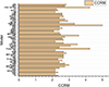 |
Figure 3 CCRM for different control techniques. |
4 Conclusion and future scope
Based on the extensive evaluation of different control models, it can be observed that these models vary widely in terms of their performance characteristics. When evaluated, it was observed that Fuzzy DCC, FTE PC, PI ESO, and PWM HC is able to achieve low cost of deployment, while PI CDL, Fuzzy DCC, PI ESO, and FOG TF PID have lower computational complexity, thus can be deployed for cost-aware and simplistic use cases. While, MPC MPPT, RIC, Fuzzy DCC, DRL, NMPC, PI ESO, COT, DCC IC, and QFT have higher conversion efficiency, and DRL, PI ESO, and FOG TF PID have lower computational delays, thus can be used for high-performance and high-speed deployments.
Models proposed in IOM, MPC DPPC, PI DAB, DRL, PI ESO, and FOG TF PID are highly scalable, thus can be deployed for large-scale applications. To further simplify model selection process, a novel Converter Control Rank Metric CCRM is evaluated, based on which, it was observed that PI ESO, Fuzzy DCC, FOG TF PID, DRL, FTE PC, and PWM HC are capable of achieving lower cost, with lower complexity, and higher conversion efficiency levels. These models also showcase lower delay but can be used large-scale scenarios. Thus, these models must be used by control system designers to develop high-efficiency converter control circuits.
In future, these models must be validated on larger circuits, and can be improved via integration of hybrid bioinspired techniques, that will assist in identification of component ratings under different load types. This performance can also be improved via integration of Auto Encoders, Q-Learning, and other transformer-based methods, which will assist in efficient power distribution with better computational performance under higher component-density scenarios.
References
- Sadabadi M.S. (2021) A distributed control strategy for parallel DC-DC converters, IEEE Control Syst. Lett. 5, 4, 1231–1236. [CrossRef] [MathSciNet] [Google Scholar]
- Wu J., Lu Y. (2020) Decoupling and optimal control of multilevel buck DC–DC converters with inverse system theory, IEEE Trans. Ind. Electron. 67, 9, 7861–7870. [CrossRef] [Google Scholar]
- Yin Y., et al. (2020) Advanced control strategies for DC–DC Buck converters with parametric uncertainties via experimental evaluation, IEEE Trans. Circuits Syst. I Regul. Pap. 67, 12, 5257–5267. [CrossRef] [MathSciNet] [Google Scholar]
- Veerachary M., Trivedi A. (2022) Linear matrix inequality-based multivariable controller design for boost cascaded charge-pump-based double-input DC–DC converter, IEEE Trans. Ind. Appl. 58, 6, 7515–7528. [CrossRef] [Google Scholar]
- Abdel-Rahim O., Wang H. (2020) A new high gain DC-DC converter with model-predictive-control based MPPT technique for photovoltaic systems, CPSS Trans. Power Electron. Appl. 69, 2, 191–200. [CrossRef] [Google Scholar]
- Li P., Wang Y., Liu L., Li X., Zuo Z. (2022) Low frequency current-mode control for DC-DC boost converters with overshoot suppression, IEEE Trans. Circuits Syst. I Regul. Pap. 69, 11, 4702–4713. [CrossRef] [Google Scholar]
- Aranda E.D., Litrán S.P., Prieto M.B.F. (2022) Combination of interleaved single-input multiple-output DC-DC converters, CSEE J. Power Energy Syst 8, 1, 132–142. [Google Scholar]
- Esteban F.D., Serra F.M., De Angelo C.H. (2021) Control of a DC-DC dual active bridge converter in DC microgrids applications, IEEE Latin Am. Trans. 19, 8, 1261–1269. [CrossRef] [Google Scholar]
- Wang Z., Li S., Li Q. (2020) Discrete-time fast terminal sliding mode control design for DC–DC buck converters with mismatched disturbances, IEEE Trans. Ind. Inform. 16, 2, 1204–1213. [CrossRef] [Google Scholar]
- Repecho V., Olm J.M., Griñó R., Dòria-Cerezo A., Fossas E. (2021) Modelling and nonlinear control of a magnetically coupled multiport DC-DC converter for automotive applications, IEEE Access 9, 63345–63355. [CrossRef] [Google Scholar]
- Kobaku T., Rao V., Patwardhan S.C., Agarwal V. (2021) Improved set-point tracking and disturbance rejection of DC–DC converters using voltage-mode digital control, IEEE J. Emerg. Sel. Top. Power Electron. 9, 3, 3276–3286. [CrossRef] [Google Scholar]
- Silva A.W.N.D., Bezerra L.D.S., Jucá S.C.S., Pereira R.I.S., Medeiros C.M.D.S. (2020) Control and monitoring of a Flyback DC-DC converter for photovoltaic applications using embedded IoT system, IEEE Latin Am. Trans 18, 11, 892–1899. [Google Scholar]
- Wang J., Sun K., Xue C., Liu T., Li Y. (2022) Multi-port DC-AC converter with differential power processing DC-DC converter and flexible power control for battery ESS integrated PV systems, IEEE Trans. Ind. Electron. 69, 5, 4879–4889. [CrossRef] [Google Scholar]
- Loranca-Coutiño J., et al. (2021) Model-based and model-free control of DC–DC converters with high-order dynamics and limited measurements, IEEE Trans. Indus. Electron. 68, 8, 6750–6761. [CrossRef] [Google Scholar]
- Maddalena E.T., Specq M.W.F., Wisniewski V.L., Jones C.N. (2021) Embedded PWM predictive control of DC-DC power converters via piecewise-affine neural networks, IEEE Open J. Ind. Electron. Soc. 2, 199–206. [CrossRef] [Google Scholar]
- Chen N., Liu J., Ma S., Wei T. (2021) Digital current-mode controller using delta operator and advance sampling predictive control for high-frequency DC–DC switching converters, IEEE J. Emerg. Sel. Top. Power Electron. 9, 5, 6272–6281. [CrossRef] [MathSciNet] [Google Scholar]
- Hou N., Li Y. (2021) A direct current control scheme with compensation operation and circuit-parameter estimation for full-bridge DC–DC converter, IEEE Trans. Power Electron. 36, 1, 1130–1142. [CrossRef] [Google Scholar]
- Li Y., Ruan X., Zhang L., Lo Y.-K. (2020) Multipower-level hysteresis control for the class E DC–DC converters, IEEE Trans. Power Electron. 35, 5 5279–5289. [CrossRef] [Google Scholar]
- Hou N., Ding L., Gunawardena P., Zhang Y., Li Y.W. (2022) A comprehensive comparison of two fast-dynamic control structures for the DAB DC–DC converter, IEEE Trans. Power Electron. 37, 6, 6488–6500. [CrossRef] [MathSciNet] [Google Scholar]
- Liu J., Liu Z., Chen W., Su H., Zhang L. (2022) Current sharing based on incremental passivity and unknown load finite-time estimation for multilevel connected DC–DC converters, IEEE Trans. Ind. Electron. 69, 1, 713–724. [CrossRef] [Google Scholar]
- Dai Y., Luo S., Li Z. (2021) Direct power based control strategy for DAB DC-DC converter with cooperative triple phase shifted modulation, IEEE Access 9, 147791–147800. [CrossRef] [Google Scholar]
- Chinchero H., Alonso M. (2021) Using Magnetic Control of DC-DC Converters in LED Driver Applications, IEEE Latin Am. Trans. 19, 2, 297–305. [CrossRef] [Google Scholar]
- Sadabadi M.S., Mijatovic N., Trégouët J.F., Dragičević T. (2022) Distributed control of parallel DC–DC converters under FDI attacks on actuators, IEEE Trans. Ind. Electron. 69, 10, 10478–10488. [CrossRef] [Google Scholar]
- Chen N., Ma S., Yang L., Wei T. (2022) Digital V2 controller IC using delta operator and improved average predictive control for DC–DC converters with fast transient response, IEEE J. Emerg. Sel. Top. Power Electron. 10, 3, 3219–3229. [CrossRef] [Google Scholar]
- Tesaki K., Hagiwara M. (2021) Control and experimental verification of a bidirectional nonisolated DC–DC converter based on switched-capacitor converters, IEEE Trans. Power Electron. 36, 6, 6501–6512. [CrossRef] [Google Scholar]
- Al-Baidhani H., Salvatierra T., Ordóñez R., Kazimierczuk M.K. (2021) Simplified nonlinear voltage-mode control of PWM DC-DC buck converter, IEEE Trans. Energy Convers. 36, 1, 431–440. [CrossRef] [Google Scholar]
- Wang M., et al. (2021) Hybrid control strategy for an integrated DAB–LLC–DCX DC–DC converter to achieve full-power-range zero-voltage switching, IEEE Trans. Power Electron. 36, 12, 14383–14397. [CrossRef] [Google Scholar]
- Hajihosseini M., Andalibi M., Gheisarnejad M., Farsizadeh H., Khooban M.H. (2020) DC/DC power converter control-based deep machine learning techniques: Real-time implementation, IEEE Trans. Power Electron. 35, 10, 9971–9977. [CrossRef] [Google Scholar]
- Song W., Zhong M., Luo S., Yang S. (2020) Model predictive power control for bidirectional series-resonant isolated DC–DC converters with fast dynamic response in locomotive traction system, IEEE Trans. Transport. Electrific. 6, 3, 1326–1337. [CrossRef] [Google Scholar]
- Guler N., Biricik S., Bayhan S., Komurcugil H. (2021) Model predictive control of DC–DC SEPIC converters with autotuning weighting factor, IEEE Trans. Ind. Electron. 68, 109433–109443. [CrossRef] [Google Scholar]
- Adupa C., Chidambaranathan V.S. (2024) Design and performance evaluation of multilevel inverter for solar energy systems and electric vehicle charging with multi output active clamp forward converter, Sci. Technol. Energy Trans. 79, 93. [Google Scholar]
- Saurabh S., Kumar R. (2024) Optimizing PV integration: Addressing energy fluctuations through BIPV and rooftop PV synergy, Sci. Technol. Energy Trans. 79, 6. [Google Scholar]
- Mari J.L., Delay F., Voisin C., Gaudiani P. (2023) Active and passive acoustic logging applied to the detection of preferential flow in a sedimentary aquifer, Sci. Technol. Energy Trans. 78, 25. [Google Scholar]
- Le V.H., Caumon M.C., Pironon J., de Donato P., Piedevache M., Randi A, Barres O. (2023) Quantitative monitoring of dissolved gases in a flooded borehole: calibration of the analytical tools, Sci. Technol. Energy Trans. 78, 21. [Google Scholar]
- Kiemde A.F., Ferrando N., de Hemptinne J.C., Le Gallo Y., Reveillère A., Pinto J.S.R. (2023) Hydrogen and air storage in salt caverns: a thermodynamic model for phase equilibrium calculations, Sci. Technol. Energy Trans. 78, 10. [Google Scholar]
- Andrés-Martínez O., Flores-Tlacuahuac A., Ruiz-Martinez O.F., Mayo-Maldonado J.C. (2021) Nonlinear model predictive stabilization of DC–DC boost converters with constant power loads, IEEE J. Emerg. Sel. Top. Power Electron. 9, 1, 822–830. [CrossRef] [Google Scholar]
- Zheng Y., Guo J., Leung K.N. (2020) A single-inductor multiple-output buck/boost DC–DC converter with duty-cycle and control-current predictor, IEEE Trans. Power Electron. 35, 11, 12022–12039. [CrossRef] [Google Scholar]
- Tavan M., Sabahi K., Hajizadeh A., Soltani M.N., Jessen K. (2021) Overcoming the detectability obstacle in adaptive output feedback control of DC–DC boost converter with unknown load, IEEE Trans. Control Syst. Technol. 29, 6, 2678–2686. [CrossRef] [Google Scholar]
- Rocha E.M., Barra W., Lucas K.E., Medeiros R.L.P., Vaca-Benavides D.A. (2020) Design and experimental assessment of a robust voltage control for DC-DC converters considering components parametric uncertainties, IEEE Access 8, 109217–109231. [CrossRef] [Google Scholar]
- Zhuo S., Gaillard A., Xu L., Paire D., Gao F. (2020) Extended state observer-based control of DC–DC converters for fuel cell application, IEEE Trans. Power Electron. 35, 9, 9923–9932. [CrossRef] [Google Scholar]
- Merey S., Chen L. (2023) Worldwide regulations and policy trends on gas production from gas hydrates, Sci. Technol. Energy Trans. 78, 23. [Google Scholar]
- Hole S.R., Goswami A.D. (2022) Quantitative analysis of DC–DC converter models: a statistical perspective based on solar photovoltaic power storage, Energy Harvest. Syst. 9, 1, 113–121. [CrossRef] [Google Scholar]
- Xie N., Liu J., Wang Y., Yin Z., Chen C., Wang L. (2024) Synergistic adaptive control of virtual inertia and damping coefficient in virtual synchronous generators for standalone microgrid applications, Sci. Technol. Energy Trans. 79, 75. [Google Scholar]
- Hole S.R., Goswami A.D. (2022) Maintain maximum power point tracking of photovoltaic using SEPIC converter, in: 2022 2nd International Conference on Power Electronics & IoT Applications in Renewable Energy and its Control (PARC), January, IEEE, pp. 1–6. [Google Scholar]
- Mingming S., Jun M., Xiaolong X., Fan W. (2024) Research on the multi-scenario control strategy of an active distribution network based on Rotary Power Flow controller, Sci. Technol. Energy Trans. 79, 51. [Google Scholar]
- Dutta S., Johnson B. (2022) A practical digital implementation of completely decentralized ripple minimization in parallel-connected DC–DC converters, IEEE Trans. Power Electron. 37, 12, 14422–14433. [CrossRef] [Google Scholar]
- Sidorov V., Chub A., Vinnikov D., Bakeer A. (2021) An overview and comprehensive comparative evaluation of constant-frequency voltage buck control methods for series resonant DC–DC converters, IEEE Open J. Ind. Electron. Soc. 2, 65–79. [CrossRef] [Google Scholar]
- Zhang X., Zhang Z., Bao H., Bao B., Qu X. (2021) Stability effect of control weight on multiloop COT-controlled buck converter with PI compensator and small output capacitor ESR, IEEE J. Emerg. Sel. Top. Power Electron. 9, 4, 4658–4667. [CrossRef] [Google Scholar]
- Hole S.R., Goswami A.D. (2024) Design of a novel hybrid soft computing model for passive components selection in multiple load Zeta converter topologies of solar PV energy system, Energy Harvest. Syst. 11, 1, 20230029. [CrossRef] [Google Scholar]
- Tabassum S., Babu A.R.V., Dheer D.K. (2024) A comprehensive exploration of IoT-enabled smart grid systems: power quality issues, solutions, and challenges, Sci. Technol. Energy Trans. 79, 62. [Google Scholar]
- Hole S.R., Goswami A.D. (2022) Analysis and performance of solar photovoltaic energy system in India: case study, in: 2022 4th International Conference on Inventive Research in Computing Applications (ICIRCA), September, IEEE, pp. 228–234. [Google Scholar]
- Rajendra Hole S., Goswami A.D. (2023) Design GA & PSO-based high-efficiency SEPIC DC-DC converter for context-aware duty cycle control, Electric Power Comp. Syst. 1–20. [CrossRef] [Google Scholar]
- Tabassum S., Babu A.R.V., Dheer D.K. (2024) Real-time power quality enhancement in smart grids through IoT and adaptive neuro-fuzzy systems, Sci. Technol. Energy Trans. 79, 89. [Google Scholar]
- Hole S.R., Goswami A.D. (2023) Solar analytics using AWS serverless services, in: Machine learning and the Internet of things in solar power generation, CRC Press, pp. 1–20. [Google Scholar]
- Zhang L., Ding H., Tian W., Lu K. (2021) Research on five-level control scheme of hybrid-bridge bidirectional DC–DC converter, IEEE J. Emerg. Sel. Top. Power Electron. 9, 2, 1339–1349. [CrossRef] [Google Scholar]
- Zhou D., Wang J., Li Y., Zou J., Sun K. (2022) Model predictive power control of grid-connected quasi single-st, age converters for high-efficiency low-voltage ESS integration, IEEE Trans. Ind. Electron. 69, 2, 1124–1134. [CrossRef] [Google Scholar]
- Hole S.R., Goswami A.D. (2024) EPCMSDB: Design of an ensemble predictive control model for solar PV MPPT deployments via dual bioinspired optimizations, Sci. Technol. Energy Trans. 79, 8. [Google Scholar]
- Goswami A.D., Hole S.R. (2024) Analysis and comparison of the DC-DC converter with soft computing algorithm, EAI Endorsed Trans. Scalable Inf. Syst. 11, 2, 1–8. [Google Scholar]
- Li X.L., Dong Z., Tse C.K., Lu D.D.-C. (2020) Single-inductor multi-input multi-output DC–DC converter with high flexibility and simple control, IEEE Trans. Power Electron. 35, 12, 13104–13114. [CrossRef] [Google Scholar]
- Luo C., Huang S. (2020) Novel voltage balancing control strategy for dual-active-bridge input-series-output-parallel DC-DC converters, IEEE Access 8, 103114–103123. [CrossRef] [Google Scholar]
- Xia P., Shi H., Wen H., Bu Q., Hu Y., Yang Y. (2020) Robust LMI-LQR control for dual-active-bridge DC–DC converters with high parameter uncertainties, IEEE Trans. Transport. Electrific. 6, 1, 131–145. [CrossRef] [MathSciNet] [Google Scholar]
- Mayo-Maldonado J.C., Ruiz-Martinez O.F., Escobar G., Valdez-Resendiz J.E., Maupong T.M., Rosas-Caro J.C. (2021) Nonlinear stabilizing control design for DC–DC converters using lifted models, IEEE Trans. Ind. Electron. 68, 11, 10772–10783. [CrossRef] [Google Scholar]
- Braitor A.-C., Konstantopoulos G.C., Kadirkamanathan V. (2021) Current-limiting droop control design and stability analysis for paralleled boost converters in DC microgrids, IEEE Trans. Control Syst. Technol. 29, 1, 385–394. [CrossRef] [Google Scholar]
- Sebastián E., Montijano E., Oyarbide E., Bernal C., Gálvez R. (2022) Nonlinear implementable control of a dual active bridge series resonant converter, IEEE Trans. Ind. Electron. 69, 5, 5111–5121. [CrossRef] [Google Scholar]
- Mosayebi M., Khooban M.H. (2020) A robust shipboard DC-DC power converter control: concept analysis and experimental results, IEEE Trans. Circuits Syst. II: Exp. Briefs 67, 11, 2612–2616. [Google Scholar]
- Kobaku T., Jeyasenthil R., Sahoo S., Ramchand R., Dragicevic T. (2021) Quantitative feedback design-based robust PID control of voltage mode controlled DC-DC boost converter, IEEE Trans. Circuits Syst. II Exp. Briefs 68, 1, 286–290. [Google Scholar]
- Güven B., Güler N., Altin N. (2022) Modified fast terminal sliding mode control for DC-DC buck power converter with switching frequency regulation, Int. Trans. Electr. Energy Syst. 2022, 1, 5076611. [Google Scholar]
- Azizi S., Asemani M.H., Vafamand N., Mobayen S., Khooban M.H. (2021) A linear parameter varying control approach for DC/DC converters in all‐electric boats, Complexity 2021, 1, 8848904. [CrossRef] [Google Scholar]
All Tables
All Figures
|
Figure 1 (a) Rectifier, (b) inverter topologies. |
| In the text | |
|
Figure 2 (a) BVCC (b) BCCC topologies. |
| In the text | |
|
Figure 3 CCRM for different control techniques. |
| In the text | |
Current usage metrics show cumulative count of Article Views (full-text article views including HTML views, PDF and ePub downloads, according to the available data) and Abstracts Views on Vision4Press platform.
Data correspond to usage on the plateform after 2015. The current usage metrics is available 48-96 hours after online publication and is updated daily on week days.
Initial download of the metrics may take a while.