")
")
| Issue |
Sci. Tech. Energ. Transition
Volume 81, 2026
|
|
|---|---|---|
| Article Number | 5 | |
| Number of page(s) | 10 | |
| DOI | https://doi.org/10.2516/stet/2026007 | |
| Published online | 03 April 2026 | |
Regular Article
Employing an innovative design for DC air conditioners and optimizing various energy resources
Electrical Engineering Technology Department, College of Applied Industrial Technology (CAIT), Jazan University, 45142 Jazan, Kingdom of Saudi Arabia
* Corresponding author: This email address is being protected from spambots. You need JavaScript enabled to view it.
Received:
9
January
2025
Accepted:
28
January
2026
Abstract
This work minimizes the issue of traditional Air Conditioners (AC) by employing an innovative design for DC AC and optimizing energy resources, developing an adaptive Feedforward Incremental Conductance (FFINC) algorithm, and conducting experimental validation and cost-benefit analysis. The proposed AC can regulate the moisture levels in a room using an innovative structure that circulates pleasant air indoors. This innovative design represents a potential replacement for traditional AC. The authors have developed a solar air cooler suitable for the modern era that can either replace AC units under specific conditions or reduce their number when operating in hybrid mode. This design sets the distance between the water circulation area and the DC fan at 3 cm to ensure efficient air cooling. The system includes a 60 W DC fan that draws cool air containing water, which passes through a water absorber filter. This filter absorbs excess moisture, resulting in dry, cool air that takes a 90° circular path to minimize remaining moisture, thereby enhancing air quality. A 20W DC water pump and the DC fan use energy from various electrical sources. Under sunny conditions, a solar panel, connected via a DC to DC zeta converter, provides power to the DC air cooler. During cloudy weather or nighttime, an AC to DC converter is used to optimize operation in emergency situations; a battery is available to ensure uninterrupted operation.
Key words: AC to DC converter / Clean energy / Feedforward INC / Microcontroller / Solar PV system / Zeta converter
© The Author(s), published by EDP Sciences, 2026
 This is an Open Access article distributed under the terms of the Creative Commons Attribution License (https://creativecommons.org/licenses/by/4.0), which permits unrestricted use, distribution, and reproduction in any medium, provided the original work is properly cited.
1 Introduction
As nature reacts unpredictably to restore stability, Pakistan experienced devastating rainfall and landslides in 2022, affecting many lives. Simultaneously, glaciers are melting due to rising temperatures resulting from the greenhouse effect. To address these global threats, there is a growing need for green energy; however, solar panels are currently affordable [1]. To support green energy initiatives, a novel solar air cooler has been designed and is in the manufacturing stage. This system utilizes an 80-Watt solar panel to provide the required power to the air cooler during the day, using a DC to DC zeta converter. The zeta converter’s duty cycle (D) is controlled using a Feedforward Incremental Conductance (FFINC) algorithm that pulses at maximum power from the solar panel. Given that the solar panel has a nonlinear power versus voltage characteristic, a flexible approach to designing the control algorithm is essential for consistently optimizing the output DC power. Numerous algorithms are available to help explore maximum power efficiency. In [2], conventional techniques, Artificial Intelligence, and hybrid techniques are studied. In literature [3–5], Perturbation & Observation (P&O) and Hill Climbing (HC) analog to digital conversion method is used to explore the maximum power point [6]. Whereas, modified-Incremental Conductance (INC) techniques are more complex and are used in DC-to-DC applications [7, 8]. In [9], the grey wolf optimism technique is used to extract maximum power, and complex partial conditions [10, 11] are examined to get maximum power. Moreover, researchers are working with intelligent techniques in various fields to find the maximum PPT of solar photovoltaics. In [12, 13], a rule-based Maximum PPT system has been designed to run the brushless DC motor-based pump, and efficiency is appreciable under various conditions of the insolation. Moreover, a buck is a simple design and easily controls its duty cycle [14, 15], while its range is limited, whereas a zeta converter has a wide range of duty cycles. Various DC-to-DC converters are available. Solar panels were examined at CAIT electrical workshop lab 401 under various insolation, and it was found that under a minimum 200 W/m2 insolation, the open circuit voltage is 14 V, and at the maximum power point 13.4 V, whereas solar power delivered the least energy, under this case. Thus, the zeta converter is good for lowering the voltage level to 12. 5 V to charge the battery and to run the 60 W DC fan. In the literature survey, very few good publications on solar Air Conditioners (AC) are available. Lotfizadeh and Layeghi [16] have designed a small solar evaporative cooler with a 10W DC fan to circulate the cool air and evaporate the moisture using cooling pads. In [17], Samar and Salman design an evaporative cooling system to minimize the total consuming energy in kWh by AC. Whereas in [18], indirect evaporative cooling systems reduce the air’s humidity. This paper uses a two-dimensional cross-section model to pass the airflow and reduce the humidity level. In [19], Bowman et al. work on evaporative cooling in hot, dry weather. Its methods are used to reduce energy consumption. While Belarbi et al. [20] used the evaporating cooling method in the building and tower for sizing the evaporative cooling system. Al-Turki and Zaki [21] used intermittent spraying methods on the roof of the building to maintain the cooling, which is now old-fashioned. Schulz [22] developed a novel solar evaporative cooler to diminish the electrical power consumption. It is generally used in remote areas, and it fails in coastal areas where the humidity level is higher. In [23], a greenhouse evaporative cooling system is analyzed in its data, and it reduces the electrical energy while failing to control the coastal area’s humidity level. Whereas [24] investigated a novel idea to reduce electrical consumption using an advanced evaporating cooling system. Moreover, a few solar designs are available, which cannot be commercialized as they have some drawbacks compared to air conditioning. The authors have introduced some novel designs for solar AC. In this case, a cooling DC fan 60 W takes cool air from the created atmosphere (water tank) using water circulation in a particular area. A DC pump, 10 W, is able to circulate water into a pad to maintain the temperature below room temperature. Tank surrounding behaves like an adiabatic process where a change in heat is zero. Cool air contains water in the air, in other words, humidity, and the same humidity is carried by the DC fan. Thus, a novel design is required to control the humidity, and the authors did it. High pressure is required to extract the water from the air. Thus, pressure is developed using a water absorber filter, which makes a barrier of air condensing water. The arrangement of the water absorber filter has a short gap of 10 cm from the DC fan. It absorbs water and blocks the air from passing in the same direction. Thereby, a huge air pressure is developed, which evaporates the maximum water condensed while air takes another path to circulate cool air. This condensation to evaporation process is done by high-pressure development methods. Thus, a proposed high-pressure technology is novel in solar AC. Moreover, it possesses many advantages over air conditioning.
In developed countries, the demand for electricity is invariably higher, and the demand for air conditioning increases the demand for huge amounts of electrical energy. Thus, a proposed solar air conditioner is a good option that reduces more than 20 times the electrical energy demand
Both AC and the proposed AC can work together in big areas like workshops, Store rooms, Malls, etc. Thus, it can work in a hybrid condition, which again can reduce the demand for electrical energy
The proposed air cooler takes natural air and does not evaporate the heat in the atmosphere, while AC evaporate heat into the atmosphere. Again, natural threats cause the ozone (O3) layer to be dangerously reduced.
-
Heat absorbed by the system. It means a positive value, while air conditioning heat release to the system has a negative energy value.
-
It can easily develop and is naturally friendly.
In addition, the authors’ contributions are given as follows.
-
By employing a zeta converter, developing an adaptive intelligent control algorithm, optimizing the energy resource, and conducting extensive experimental validation and cost-benefit analysis, the present work fully demonstrates the feasibility and advantages of the proposed solution.
-
A set of solar power and FFINC based on an intelligent Maximum Power Point Tracker (MPPT) is developed to pulse zeta converter.
-
A unique design of the proposed AC can run in three modes under solar energy, battery energy, and AC to DC mode.
A comprehensive description of the proposed AC is given in the following sections.
2 Model description
In this section, the proposed model is explained in detail about its functions. In Figure 1, the multisource electrical power is connected to the DC fan and DC pump. There are conventional sources and non-conventional sources to continuously supply in remote areas to smooth the working of the AC. A non-conventional resource, like solar panels and batteries, while the conventional source is converted from AC to DC using a converter. Moreover, the battery supplies emergency current to the DC fan and pump. Further explanation is given in subsections.
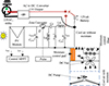 |
Figure 1 Multisource electrical energy model of proposed air conditioner. |
2.1 Non-convention resource
Light energy, or solar energy, is able to generate electrical energy using solar panels. The method to generate current is known as the photovoltaic effect. It can use the sun’s insolation to harvest DC current. The sun’s insolation breaks the barrier voltage of the semiconductor and harvests electrical current (Iph) under Standard Test Conditions (STC), which are represented as, (1)
(1)
A semiconductor-based multiple solar cells can be arranged in series and parallel to get the open circuit voltage and short circuit current. Many factors of solar cells are considered when designing panels, while temperature and insolation factors are significant. The open circuit voltage (Voc) can be estimated as, (2)
(2)
And constant ast = nkT/q (Iph,st = light current, Irs,st = reverse current, n = identity factor, k = Boltzmann constant, T = Temperature, and q = Charge).
Moreover, important short circuit current parameters are given as,![Mathematical equation: $$ {I}_{\mathrm{sc}}={I}_{\mathrm{ph},\mathrm{st}}-{I}_{\mathrm{rs},\mathrm{st}}\enspace \left[{e}^{\frac{{I}_{\mathrm{sc},\mathrm{st}}.{R}_{\mathrm{s},\mathrm{st}}}{{a}_{\mathrm{st}}}}-1\right]-\frac{{I}_{\mathrm{sc},\mathrm{st}}.{R}_{\mathrm{s},\mathrm{st}}}{{R}_{\mathrm{sh},\mathrm{st}}}. $$](/articles/stet/full_html/2026/01/stet20250015/stet20250015-eq3.gif) (3)
(3)
And constant (Rs = series resistance and Rsh = shunt resistant).
The above equations are used to find the parameter values and ratings of the solar panel. It has nonlinear characteristics. Thereby, a maximum power point tracking system is used to extract the maximum power with constant voltage using a solar converter. In the literature, more than 30 DC-to-DC converter configurations are accessible. Solar charge is somehow different from the DC to DC converter. Solar photovoltaic power characteristics are nonlinear. Thus, it needs an algorithm to continuously explore maximum power at the converter’s input side. The proposed work is to use a zeta converter-based solar charger. A zeta converter shows satisfactory performance under all conditions of solar insolation. It requires two inductors with the same rating. At the same time, three capacitors, Cin, Cc, and Co, respectively, are used with control switch MOSFET Q3 and uncontrolled switch diode D. The theoretical and practical data are given in Table 1. The solar charge is in a continuous current mode of operation, and its duty cycle can be varied as solar insolation is varied. Mathematically, the duty cycle (DT) can be evaluated as, (4)
(4)
Zeta converter constraints.
And (Vo = ouput voltage, Vmax = voltage at MPPT). (5)
(5)
Moreover, the solar chargers can work under step-down and step-up voltage, depending on the duty cycle. Instead, it is a non-conventional resource that needs the Sun’s insolation.
2.2 AC supply
AC supply is converted to DC via a DC converter. There are more than 100 configurations available in the literature. The authors take a simple structure to design an isolated 220 V AC to 12 V DC bridge converter, which is shown in Figure 2. A 7816 voltage regulator is used in the given circuit to maintain and regulate the 12 V DC output. A simple 220 V AC steps down its voltage to 12 V using a down transformer, and 12 V AC passes through a diode to a converter 12 V DC with ripple. The ripple can be mitigated by an electrolyte capacitor, and in series with the circuit at the door of the output, a voltage regulator 7812 is mounted. Practical detail is given in Table 2.
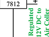 |
Figure 2 DC regulated voltage circuit under AC to DC conversion of electrical power. |
AC to DC converter constraints.
2.3 Battery
A battery is a storage cell of DC current, which is the result of electrochemistry. Numerous classes of batteries are available in the market. In the proposed hardware model, a lead-acid battery is used to work in emergency conditions in remote areas. In the presence of full or partial insolation, solar panels charge the battery via a zeta converter, which has a wide range of duty cycles to maintain the DC output. A 12 V, 35 Ah lead acid battery can discharge at 11.5 V in 2–3 h, while it can take 20–30 min to recharge up to 12 V under full solar insolation.
2.4 Proposed air conditioner
A multisource AC is shown in Figure 1, where a solar panel supplies DC current to the DC fan and DC pump via a DC to DC zeta converter in the day, while at night, a 220 V, 60 Hz single-phase. An AC to DC converter is used to run the air cooler, and during the emergency period, the DC battery supplies the current to run the system in the remote area. Hot air or humid air is taken from outside and circulated to the room 12 × 12 ft2 via a cool water surface area. Hot or humid air passes from the water tank, which is covered by the jute pad. Jute pad makes the system cool air and does not exchange the heat ΔQ. It behaves like an adiabatic system, where a system is unable to exchange heat with its surroundings. A jute pad is wet by circulating water circulated by the DC pump. A 4–7 m copper pipe is mounted inside the tank surface to circulate cool water. A top coil of Cooper pipe has a small hole at a certain distance on only three sides, which works as a fountain. Figures 3a and 3b are depicted to understand the internal construction of the proposed multisource electrical energy air cooler. Where a proposed cooler has two sections; in section (a), water circulates through a copper pipe and is wetted to the jute pad (b) to cool the high-temperature air. The jute pads are able to maintain a lower temperature when water is circulating. The whole surrounding in section (a) system behaves as an adiabatic process where the change in temperature is zero. The atmospheric air temperature is higher, and pressure is lower, where in section (a) of the AC, low temperature and high pressure are due to the high-speed DC fan. Thus, air gases in this situation become liquid, which makes the room highly humid and cooler.
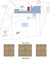 |
Figure 3 Physical structure of proposed air conditioner show top view in (a) and internal jute pad in (b). |
Figure 3a illustrates the authors’ innovative concept for reducing humidity. When moist air is drawn from the water tank and circulated in the space, it is 12 × 12 ft. In contrast to the water absorber in front of the DC fan, which lowers the moisture level so that further air has no direct path to circulate, a DC fan pushes high-pressure, moist air in an attempt to follow a straight path. Thus, air rises, releases its water content once more, and turns 90° to pass through a rectangular opening. Circulates chilly air. All of these were accomplished via creative air cooler construction and strategic DC fan positioning. Whereas in Figure 3b, jute pads are shown. It maintains the internal temperature of the proposed air conditioning. It is mounted on three sides of the cooler.
3 Control algorithm
In this work, three modes of controlling the electrical energy source are verified. First test on solar energy where a DC to DC converter is required to feed the DC current to the air cooler, and under AC supply, an AC to DC converter is needed, whereas in emergency conditions, when solar irradiation is low, or the AC supply is off, a continuous DC battery supplies the electrical energy to the DC air cooler. The following control algorithms are given as
3.1 Maximum power point tracking control algorithm
An algorithm for controlling the output voltage of a DC-to-DC zeta converter using FFINC is designed. A machine language C++-based intelligent program is also developed to design the maximum PPT and burn it into the microcontroller. It evaluates the signals and controls the duty cycle under all solar insolation conditions.
In Figure 4, an intelligent algorithm is developed using a duty cycle (D) to extract maximum power from an 80 W photovoltaic panel, as shown in equation (4). Two analog input parameters, voltage (v) and current (i), are sensed, and a delay or memory (M) is utilized to determine the output voltage (vo) and output current (io). These parameters are used to calculate di/dv and to identify the three conditions necessary for achieving maximum power from the photovoltaic panels. A constant d value is predefined and conditionally fed into the duty cycle (D) to pulse at maximum power. A zeta converter is controlled to charge a 12 V battery, and if the battery voltage reaches 13 V, it sends feedback signals to cease the firing.
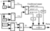 |
Figure 4 Control of duty cycle using Feedforward Incremental Conductance. |
3.2 AC to DC converter control algorithm
An isolated AC-to-DC converter is proposed to control the 12 V DC. A 220 V AC step down to more than 12 V, as some losses due to the internal resistance of the diode. 12 V AC now passes through a full-wave bridge circuit, which converts 12 V DC, including ripples. An electrolyte capacitor, 2000 microfarad, is connected in parallel to the bridge to mitigate the ripples, and finally, a 7812 voltage controller is installed before the load to regulate its voltage. This is an automated system based on the load demand.
3.3 Emergency control algorithm
A battery is used in emergency conditions to run the DC air cooler. Batteries are charged using the solar system or an AC-to-DC converter. It is used when the solar insolation supplies insufficient power at that time, the battery provides its own energy to compensate for power cuts and maintain the DC fan’s and pump’s speed. Moreover, batteries can supply DC power under sandstorms or any natural disaster for seamless control of the proposed air cooler.
Table 3 presents multisource power-based results to show its characteristics under various control powers. Where all the voltage and current inputs and outputs are mentioned, comparative results enhance the trade of novel DC AC and satisfy the customer (Figs. 5 and 6).
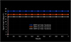 |
Figure 5 Open circuit voltage under various conditions of solar insolation. |
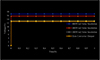 |
Figure 6 Performance of maximum power point tracking system under various conditions of solar insolation. |
A comparative result.
4 Results and discussion
A lab model 80 W includes a DC pump and fan with multisource electrical energy, such as a solar, AC supply, and battery source, under emergency conditions. An analysis of the results was performed using a digital oscilloscope, and some results were obtained using a clammed tester and digital LCD hygrometer, including a thermometer. In Table 4, complete details of the hardware are given.
Hardware parameters.
4.1 Performance analysis using DSO
In solar sources of energy under 1000 W/m2, 500 W/m2, and 200 W/m2, insolation open circuit voltage are shown in Figures 5–7, where DSO results have 5 V/division. At 1000 W/m2 insolation, the open circuit voltage is recorded at 19.2 V; at partially insolated conditions, it is recorded at 17 V; at 200 W/m2, it is recorded at 14 V. The solar panel gives satisfactory results. Moreover, in Figure 8, the maximum power point voltage is recorded as 18.4 V in yellow to generate a duty cycle and gives a constant output voltage of 12.5 V in green to charge the lead acid battery. A DSO having 5 V/division under this mode of operation. Under AC supply source input 220 V rms value, and the output is 12.8 V, with an output having 10 V/division. An AC to DC converter adjusts the DC 12 V output shown in Figure 9. The performance of the AC to DC converter is satisfactory, and the DC AC runs at a constant speed, whereas under emergency conditions, a battery is supplied to the DC source of the DC AC. The battery’s output voltage is in green in Figure 10, 5 V/division.
 |
Figure 7 A solar panel open circuit voltage under various irradiations 1000 W/m2, 500 W/m2, and 200 W/m2, respectively. |
 |
Figure 8 Input voltage of solar panel and output voltage of zeta converter under load DC fan and DC pump. |
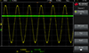 |
Figure 9 AC input voltage and output voltage of DC converter. |
 |
Figure 10 Under emergency conditions, the DC battery voltage. |
4.2 Performance analysis using digital meters
Figures 11–14, the performance of the proposed DC air cooler is given. The Relative Humidity (RH) in percent and temperature in degrees Celsius of outside surroundings, inside the Solar AC, and the inside room are recorded for 50 min at the peak hours. In the Jazan atmosphere (Southern part of the Kingdom of Saudi Arabia) in February, the relative humidity is recorded 74%, while inside the water tank of a proposed solar AC, it is increased up to 90%, and outside the cooler or inside the room, nearly 66% is recorded for three turns of copper coil through which water is circulating. It can be observed in Figure 11. However, in Figure 13, RH is recorded at 65% inside the room for six turns of the copper coil. It is because water circulates through the copper coil for a long time, while inside, the surface of the water drops slowly to wet the jut pad. Inside the room, RH is controlled by a novel structure of DC fan circulate air, which is already discussed in the model description section D. In Figure 12, atmospheric temperature is recorded at 39 °C, while inside the water tank is recorded at 26–24 °C and inside the room is 27 °C for three turns of copper coil. In Figure 14, inside the water tank, 26–22 °C is recorded; as a result, the same temperature is recorded inside the room. These results show that the DC-AC novel structure is a good trade option. Moreover, under hybrid conditions, the performance of the results is analyzed. It is proposed that the novel construction DC-AC can work in hybrid conditions inside workshops, hospitals, offices, and big areas. In Figure 15, RH reduces slightly as split AC is switched on and a temperature of 28 °C is set, while the temperature reduces substantially and the room temperature is recorded up to 20 °C, which is shown in Figure 16.
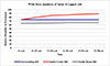 |
Figure 11 Performance of relative humidity in percentage of DC air cooler under three turns of copper coil. |
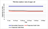 |
Figure 12 Performance of temperature of DC air cooler under three turns of copper coil. |
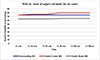 |
Figure 13 Performance of relative humidity in percentage of DC air cooler under six turns of copper coil. |
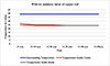 |
Figure 14 Performance of temperature of DC air cooler under six turns of copper coil. |
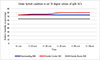 |
Figure 15 Performance of relative humidity of DC air cooler under hybrid conditions. |
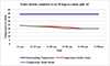 |
Figure 16 Performance of temperature under hybrid condition of DC air cooler. |
Thus, authors have suggested running the proposed solar air cooler as a hybrid condition to save electricity bills. The proposed air cooler consumes an electricity bill of 3 $ while the split AC consumes an electricity bill of $70–$80 per month.
5 Conclusion
It is seen that multisource electrical energy is useful in remote areas and in urban areas. A seamless supply of DC current is able to satisfy the customer to opt for a proposed model against AC, either in single-mode or hybrid mode. An 80 W, 12 V DC fan and pump under solar conditions, the installation cost is compared to an air conditioner, which is more, while the electricity bill per year is zero. On the other hand, 700 $/year to 800 $/year have to pay. Moreover, an AC to DC supply installation costs less than AC and generates an electricity bill per year of 36 dollars/year, less than 5% of the AC bill. The proposed DC air cooler has been observed as a novel structure that minimizes relative humidity. A DC air cooler has two sections, and each section works satisfactorily. In the first section, multisource electrical energy is used to feed the DC fan and pump to circulate the pleasant air inside the room, while the second section possesses a water tank where the copper coil is wound over a 3–6-layer circular path to circulate the water, and the upper part of the coil has a hole to wet the jute pad. The pads keep the intake air cool for an extended period. Thus, the work of DC AC is economically good for both developing and developed countries. The performance of all sections of solar AC is satisfactory and reliable.
References
- Pratik T., Anurag T., Atul K. (2024) GREENSKY: A fair energy-aware optimization model for UAVs in next-generation wireless networks, Green Energy Intell. Transp. 3(1), 100130. https://doi.org/10.1016/j.geits.2023.100130. [Google Scholar]
- Po-Cheng C., Po-Yen C., Yi-Hua L., Jing-Hsiao C., Yi-Feng L. (2015) A comparative study on maximum power point tracking techniques for photovoltaic generation systems operating under fast-changing environments, Solar Energy 119, 261–276. https://doi.org/10.1016/j.solener.2015.07.006. [Google Scholar]
- Madhu G.M., Chintamani V., Chirag N.M. (2021) Adaptive step size based drift-free P&O algorithm with power optimiser and load protection for maximum power extraction from PV panels in stand-alone applications, IET Renew. Power Gener. 15, 6, 1270–1285. [Google Scholar]
- Bairami S., Salimi M., Mirabbasi D. (2023) A novel method for maximum power point tracking of the grid-connected three-phase solar systems based on the PV current prediction, Chin. J. Electron. 32, 2, 353–364. https://doi.org/10.23919/cje.2021.00.218. [CrossRef] [Google Scholar]
- Elgendy M.A. (2016) Comparative investigation on hill climbing MPPT algorithms at high perturbation rates, in 7th International Renewable Energy Congress (IREC), Hammamet, Tunisia, pp. 1–6. https://doi.org/10.1109/IREC.2016.7478939. [Google Scholar]
- Weiwei Z., Liqun S., Pengwei L., Hangchen G. (2018) Modified hill climbing MPPT algorithm with reduced steady-state oscillation and improved tracking efficiency, J. Eng. 17, 1878–1883. https://doi.org/10.1049/joe.2018.8337. [Google Scholar]
- Ez-Zghari M., Smail C., El Youssfi N., Tarik Z.K., El Khadiri A.T. (2022) Optimized energy output from a PV system using a modified incremental conductance algorithm for rapidly changing insolation, in: Motahhir S., Bossoufi B. (eds.), Digital technologies and applications, Springer, Cham, pp. 649–658. https://doi.org/10.1007/978-3-031-02447-4_67. [Google Scholar]
- Sheikh S.H.A., Karami M., Gholami M., Mirzaei R. (2022) Improving MPPT performance in pv systems based on integrating the incremental conductance and particle swarm optimization methods, Iran J. Sci. Technol. Trans. Electr. Eng. 46, 27–39. https://doi.org/10.1007/s40998-021-00459-0. [Google Scholar]
- Ibrahim S.M., Pei C.C., Dawit F.T., Ramadhani K.S., Kuo L.L., Jia-Fu L. (2022) An enhanced grey wolf optimization algorithm for photovoltaic maximum power point tracking control under partial shading conditions, IEEE Open J. Ind. Electron. Soc. 3, 392–408. https://doi.org/10.1109/OJIES.2022.3179284. [Google Scholar]
- Ali M.E., Al-Saud M.S., Abokhalil A.G., Farh H.M.H. (2020) Simulation and experimental validation of fast adaptive particle swarm optimization strategy for photovoltaic global peak tracker under dynamic partial shading, Renew. Sustain. Energy Rev. 124, 109719. https://doi.org/10.1016/j.rser.2020.109719. [Google Scholar]
- Abdelilah C., Aboubakr E.H., Saad M., Abdelaziz E.G., Aziz D. (2021) Development of an improved gmppt based on scanning method for PV system operating under a dynamic partial shading conditions, Technol. Econ. Smart Grids Sustain. Energy 6, 19. https://doi.org/10.1007/s40866-021-00118-7. [Google Scholar]
- Muhammad H.Z., Noman M.K., Adeel F.M., Majad M. (2021) Bio-inspired optimization algorithms based maximum power point tracking technique for photovoltaic systems under partial shading and complex partial shading conditions. J. Clean. Prod. 309, 127279. https://doi.org/10.1016/j.jclepro.2021.127279. [Google Scholar]
- Mashhood H., Alhazmi W.H., Zakri W. (2022) A fuzzy rule based control algorithm for MPPT to drive the brushless DC motor based water pump, J. Intell. Fuzzy Syst 42, 2, 1003–1014. https://doi.org/10.3233/JIFS-189767. [Google Scholar]
- Azer P., Emadi A. (2020) Generalized state space average model for multi-phase interleaved buck, boost and buck-boost DC-DC converters: Transient, steady-state and switching dynamics, IEEE Access 8, 77735–77745. https://doi.org/10.1109/ACCESS.2020.2987277. [Google Scholar]
- Pei L., Meng X., Li X. (2024) A novel digital-controlled current-mode single-inductor-multiple-output buck converter with individual output overload protection, IEEE Trans. Very Large Scale Integr. (VLSI) Syst. 32, 957–961. https://doi.org/10.1109/TVLSI.2023.3343763. [Google Scholar]
- Lotfizadeh H., Layeghi M. (2014) Design and performance analysis of a small solar evaporative cooler, Energy Efficiency 7, 55–64. https://doi.org/10.1007/s12053-013-9199-5. [Google Scholar]
- Samar J., Salman A. (2011) Evaporative cooling as an efficient system in Mediterranean region, Appl. Therm. Eng. 31, 14–15. https://doi.org/10.1016/j.applthermaleng.2011.04.026. [Google Scholar]
- Bin Z., Chunmei G., Tong C., Qi S., Jian L., Yuwen Y. (2019) Development of an experimental validated model of cross-flow indirect evaporative cooler with condensation, Appl. Energy 252, 113438. https://doi.org/10.1016/j.apenergy.2019.113438. [Google Scholar]
- Bowman N., Lomasl K., Cook M., Eppel H., Ford B., Hewitt M., Cucinella M., Francis E., Rodriguez E., Gonzalez R., Alvarez S., Galata A., Lanarde P., Belarbi R. (1997) Application of passive downdraught evaporative cooling (PDEC) to non-domestic buildings, Renewable Energy 10, 191–196. [Google Scholar]
- Belarbi R., Ghiaus C., Allard F. (2006) Modeling of water spray evaporation: application to passive cooling of buildings, Sol. Energy 80, 1540–1552. [Google Scholar]
- Al-Turki A.M., Zaki G.M. (1991) Energy saving through intermittent evaporative roof cooling, Energy Build. 17, 35–42. [Google Scholar]
- Schulz S.L. (2000) Evaporative cooler solar retrofit kit, U.S. Patent 6101716. [Google Scholar]
- Kittas C., Bartzanas T., Jaffrin A. (2001) Greenhouses evaporative cooling: measurement and data analysis, Trans ASAE 44, 3, 683–689. [Google Scholar]
- Khandelwal A., Talukdar P., Jain S. (2011) Energy savings in a building using regenerative evaporative cooling, Energy Build. 43, 581–591. [Google Scholar]
All Tables
All Figures
|
Figure 1 Multisource electrical energy model of proposed air conditioner. |
| In the text | |
|
Figure 2 DC regulated voltage circuit under AC to DC conversion of electrical power. |
| In the text | |
|
Figure 3 Physical structure of proposed air conditioner show top view in (a) and internal jute pad in (b). |
| In the text | |
|
Figure 4 Control of duty cycle using Feedforward Incremental Conductance. |
| In the text | |
|
Figure 5 Open circuit voltage under various conditions of solar insolation. |
| In the text | |
|
Figure 6 Performance of maximum power point tracking system under various conditions of solar insolation. |
| In the text | |
|
Figure 7 A solar panel open circuit voltage under various irradiations 1000 W/m2, 500 W/m2, and 200 W/m2, respectively. |
| In the text | |
|
Figure 8 Input voltage of solar panel and output voltage of zeta converter under load DC fan and DC pump. |
| In the text | |
|
Figure 9 AC input voltage and output voltage of DC converter. |
| In the text | |
|
Figure 10 Under emergency conditions, the DC battery voltage. |
| In the text | |
|
Figure 11 Performance of relative humidity in percentage of DC air cooler under three turns of copper coil. |
| In the text | |
|
Figure 12 Performance of temperature of DC air cooler under three turns of copper coil. |
| In the text | |
|
Figure 13 Performance of relative humidity in percentage of DC air cooler under six turns of copper coil. |
| In the text | |
|
Figure 14 Performance of temperature of DC air cooler under six turns of copper coil. |
| In the text | |
|
Figure 15 Performance of relative humidity of DC air cooler under hybrid conditions. |
| In the text | |
|
Figure 16 Performance of temperature under hybrid condition of DC air cooler. |
| In the text | |
Current usage metrics show cumulative count of Article Views (full-text article views including HTML views, PDF and ePub downloads, according to the available data) and Abstracts Views on Vision4Press platform.
Data correspond to usage on the plateform after 2015. The current usage metrics is available 48-96 hours after online publication and is updated daily on week days.
Initial download of the metrics may take a while.