")
")
| Issue |
Sci. Tech. Energ. Transition
Volume 80, 2025
|
|
|---|---|---|
| Article Number | 34 | |
| Number of page(s) | 20 | |
| DOI | https://doi.org/10.2516/stet/2025013 | |
| Published online | 21 April 2025 | |
Regular Article
Integrating ANN and ANFIS for effective fault detection and location in modern power grid
Electrical Engineering, Maulana Azad National Institute of Technology, Bhopal, 462003, Madhya Pradesh, India
* Corresponding author: This email address is being protected from spambots. You need JavaScript enabled to view it.
Received:
8
November
2024
Accepted:
18
March
2025
Abstract
The increasing complexity and demand for reliability in modern power systems necessitate advanced techniques for fault detection, classification, and location. This work presents a comprehensive study on the application of Artificial Neural Network (ANN) and Adaptive Neuro-Fuzzy Inference System (ANFIS) for fault management in power systems. ANFIS, combining the benefits of neural networks and fuzzy logic, offers a robust framework for handling the non-linearities and uncertainties inherent in power system faults. The proposed method leverages historical fault data to train the ANFIS model, enabling it to accurately detect, classify, and locate various types of faults, including line-to-ground, line-to-line, and three-phase faults. The model’s performance is evaluated using a simulated power system environment, and its effectiveness is validated through extensive testing under different fault scenarios. Results demonstrate that the ANFIS-based approach achieves high accuracy in fault detection and classification, significantly reducing the response time. Additionally, the system exhibits a strong capability in pinpointing fault locations with minimal error margins. This research underscores the potential of ANFIS as a powerful tool for improving the consistency and competence of fault management in power systems. The findings suggest that integrating ANFIS into existing protection schemes can lead to improved operational efficiency (97–99%), whereas in case of ANN, the efficiency is (92–95%) resilience and reduced downtime. Future work will focus on real-time implementation and the incorporation of ANFIS with other smart grid technologies to further augment fault management capabilities.
Key words: Detection of faults / Classification of faults / Location of faults / Power system / ANN / ANFIS
© The Author(s), published by EDP Sciences, 2025
 This is an Open Access article distributed under the terms of the Creative Commons Attribution License (https://creativecommons.org/licenses/by/4.0), which permits unrestricted use, distribution, and reproduction in any medium, provided the original work is properly cited.
1 Introduction
Modern power systems are integral to the functioning of contemporary society, underpinning everything from residential electricity supply to industrial operations [1]. As these systems grow in complexity and scale, ensuring their reliability and stability becomes increasingly challenging. One of the critical aspects of maintaining power system integrity is the precise detection, classification, and location of faults [2]. Faults in power systems can lead to significant disruptions, equipment damage, and economic losses [3]. Traditional fault management methods, while effective to some extent, often struggle with the non-linear and dynamic nature of power system faults [4]. This necessitates the development of more sophisticated and adaptive techniques capable of addressing these challenges focused on fault detection and classification in power lines using Artificial Neural Network (ANN) and Adaptive Neuro-Fuzzy Inference System (ANFIS) [5]. The main finding of this study was the successful application of ANFIS. However, a limitation of this study could be the lack of real-time implementation of the proposed method, which may affect its practical applicability. Developed an intelligent system for power transformer fault identification based on optimized ANFIS and association rules [5]. The study demonstrated the effectiveness of the proposed system in accurately diagnosing power transformer faults. A limitation of this study could be the complexity and computational requirements of the optimized ANFIS model, which may hinder its real-time application. Tabassum et al. proposed a novel methodology for fault analysis in transmission systems employing Discrete Wavelet Transform (DWT) and ANFIS [6]. The main finding of this study was the improved accuracy in fault detection and location using the combined DWT and ANFIS approach [7]. A limitation of this study could be the reliance on accurate fault data for training the ANFIS model, which may not always be readily available [8]. Yuan et al. conducted a comparative investigation of ANFIS, ANN, and Hybrid procedures for advanced fault parameter analysis in transmission lines [9]. The study highlighted the strengths and weaknesses of each method in fault detection tasks [10]. A limitation of this study could be the limited scope of comparison, as other advanced fault detection methods may have been excluded. Rao et al. proposed a fault location detection method in UG cables based on the Wavelet and ANFIS procedures [11]. The main finding of this study was the successful application of the proposed method for fault location detection in UG cables. A limitation of this study could be the potential challenges in implementing the Wavelet-ANFIS approach in practical underground cable systems, which may require further validation and testing [12]. The study by Elbaset and Hiyama focused on fault analysis in power transmission lines employing a smart distance relay system [13]. The study may be limited by the specific application of the intelligent distance electrical relay system and its effectiveness in different types of faults. Kumar et al. explored fault analysis in power allocation smart grids utilizing data from smart meters [14]. The study’s outcome may be limited by the accessibility and accuracy of data from smart meters for fault detection and location. Kumar et al. focused on high-impedance fault analysis in the Nigerian 330 kV topology using an ANFIS. The study’s applicability may be limited to the specific context of the Nigerian 330 kV transmission network and the effectiveness of the ANFIS in other settings. Khaleghi et al. discussed the implementing of machine learning procedures for fault analysis in power lines [15]. The review may be limited by the scope of machine learning methods covered and the depth of analysis for specific fault detection and classification scenarios [16]. Babu et al. focused on momentary fault area location and fault organization in distribution schemes using wavelet and ANFIS. The study’s findings may be limited by the specific application of wavelet transform and ANFIS in transient fault area location and classification, potentially requiring further validation in different scenarios. Babu et al. proposed a technique that combines DWT and ANFIS for fault analysis in distribution systems [17]. The method showed promising results in exactly finding and distinguishing faults [18]. While the proposed technique showed effectiveness in fault detection and classification, the study did not compare the performance of the DWT-ANFIS approach with other existing methods, limiting the assessment of its superiority in real-world applications. Hong and Cabatac utilized ANN for fault analysis in electrical transmission structures [19]. The study demonstrated the potential of ANN in exactly recognizing and categorizing faults in power systems. The study focused solely on the application of ANN for fault analysis without considering the integration of other techniques or methods, potentially overlooking the benefits of combining multiple approaches for enhanced fault diagnosis accuracy [20]. The ANFIS emerges as a promising solution in this context. ANFIS combines the learning expertise of ANN with the reasoning and handling of uncertainties inherent in fuzzy logic systems [21]. This hybrid approach enables the creation of models that can gather information from historic fault data and adapt to new fault scenarios with high accuracy [22]. By leveraging ANFIS for fault analysis, power system operators can achieve more reliable and efficient fault management. This paper explores the application of ANFIS in power systems, demonstrating its potential to enhance fault management processes and contribute to the overall stability and reliability of power grids.
Fault detection, classification and location estimation for different lengths of a power grid. The major contribution of the research
-
Developed an adaptive protection scheme using ANN and ANFIS.
-
The proposed ANFIS technique for fault detection is very fast compared to other techniques and reliable as depicted in Section 7.
-
Performance of system under varying line length and operation condition in microgrid with low noise with proves the robustness of the system.
-
The fault detection time is more for three phase faults as compared to the single-phase fault as shown in the results.
The results are validated in real-time using Opal-RT. The paper is structured as follows: Section 2 provides an overview of existing studies on the application of ANN and ANFIS in power system protection. Section 3 provides the adaptive ANN based protection method. Section 4 provides the adaptive ANFIS based protection method. Section 5 provides the 11 KV transmission model. Section 6 provides the fault type classification and detection of the fault. Section 7 provides the results and the discussions of this research. Conclusion is provided in Section 8.
2 Related works
This section provides an overview of existing studies on the application of ANN and ANFIS in power system protection.
-
Meng et al. [23]: This study suggests and evaluates the effectiveness of various measures implemented on natural gas pipelines to mitigate the detrimental effects of DC ground current, focusing on strategies to reduce corrosion and improve the long-term integrity of pipeline systems.
-
Kai et al. [24]: This research article explores the use of image transformation techniques for identifying partial discharge sources in vehicle cable terminals of high-speed trains, aiming to enhance the accuracy and efficiency of fault detection in electrical systems.
-
Chenxi et al. [25]: This research article develops a multi-occupant dynamic thermal comfort monitoring robot system that utilizes real-time sensor data and adaptive algorithms to assess and optimize the thermal comfort levels of multiple individuals in shared environments.
-
Jiang et al. [26]: This research article proposes a compensation approach for magnetic encoder errors by leveraging an improved Deep Belief Network (DBN) algorithm to enhance accuracy and reliability in encoding systems.
-
Yaohui Lu et al. [27]: This article explores an innovative approach to maintenance optimization by introducing an adaptive maintenance window-based opportunistic maintenance strategy. This approach integrates operational reliability and cost considerations to enhance the efficiency of maintenance scheduling. By dynamically adjusting maintenance windows based on system conditions and performance metrics, the strategy aims to minimize downtime and maintenance costs while ensuring reliable system operation. This study provides a framework for identifying optimal maintenance opportunities, leveraging data-driven techniques to balance reliability and cost-effectiveness. The proposed methodology is particularly relevant for complex systems where traditional maintenance schedules may not adequately address variability in operational conditions.
-
Tong et al. [28]: This article proposes an intelligent fault diagnosis method for rolling bearings using Gramian Angular Difference Field (GADF) and an Improved Dual Attention Residual Network to enhance feature extraction and classification accuracy.
-
Ju et al. [29]: This article presents a quantized predefined-time control strategy for heavy-lift launch vehicles, addressing challenges posed by actuator faults and rate gyro malfunctions.
-
Wang et al. [30]: This article presents an advanced method for elevator fault diagnosis by integrating digital twins with Physics-Informed Neural Networks (PINNs) and Enhanced Relational Graph Convolutional Networks (e-RGCN).
-
Zhang et al. [31]: This article introduces an asymmetric hybrid phase-leg Modular Multilevel Converter (MMC) designed to achieve reduced size, lower cost, and enhanced DC fault-blocking capability for power systems.
-
Zhang et al. [32]: This article explores Series-Shunt Multiport Soft Normally Open Points, focusing on their application in enhancing power system flexibility, reliability, and operational efficiency.
-
Sun et al. [33]: This article presents an on-line imaging sensor system utilizing magnetic deposition and flowing dispersion techniques to monitor and analyze wear debris features in mechanical systems.
-
Miaofen et al. [34]: This article introduces the Adaptive Synchronous Demodulation Transform (ASDT) for effectively analyzing multicomponent signals in machinery fault diagnostics.
-
Hang et al. [35]: This article presents a method for diagnosing interturn short-circuit faults and implementing fault-tolerant control in Dual Three-Phase Permanent Magnet Synchronous Motors (DTP-PMSM) using subspace current residuals.
-
Hang et al. [36]: This article presents an enhanced fault diagnosis method for Permanent Magnet Synchronous Machine (PMSM) systems by integrating lightweight multisource information through data layer fusion.
-
Ni et al. [37]: This research proposes an explainable neural network that integrates the Jiles-Atherton and nonlinear auto-regressive exogenous models for accurate modeling of universal hysteresis.
-
Fan et al. [38]: This research introduces a novel reliability optimization design method combining rough set theory and a hybrid surrogate model to improve system performance.
-
Zhang et al. [39]: This research proposes an event-trigger-based resilient distributed energy management approach to protect smart grid cyber-physical systems against False Data Injection (FDI) and Denial-of-Service (DoS) attacks.
-
Zhi et al. [40]: This research article proposes a localized fault detection method for gearboxes by analyzing meshing frequency modulation patterns.
-
Hu et al. [41]: This article provides a comprehensive review of fault detection techniques for point machines, highlighting current challenges and offering perspectives for future research.
-
Lin et al. [42]: This research article proposes an optimized CatBoost-based method for identifying imbalanced industrial loads, utilizing entropy features to improve classification accuracy and efficiency in load monitoring and fault detection systems.
-
Lin et al. [42]: This research article develops a degradation twin modeling approach for assessing the performance of rolling bearings, considering the interdependent evolution of faults, and applies it to improve fault detection and prediction in mechanical systems using signal processing techniques.
-
Huang et al. [43]: This research article proposes a novel approach for surface defect detection by combining spatial deformable convolution with a dense feature pyramid to improve the accuracy and robustness of defect recognition across different scales and shapes.
-
Qiao et al. [44]: This research article proposes a multihead attention-based self-supervised representation model for detecting anomalies in industrial sensor data, leveraging attention mechanisms to capture complex patterns and improve detection accuracy without relying on labelled data.
-
Rong et al. [45]: This research article proposes a virtual external perturbance-based method for impedance measurement of grid-connected converters, aiming to enhance the accuracy and reliability of grid integration by analyzing the converter’s impedance response under controlled perturbations.
-
Rong et al. [46]: This research article proposes an asymmetric sampling disturbance-based universal impedance measurement method for converters, aiming to improve the accuracy and efficiency of impedance identification across various converter systems by leveraging sampling disturbances.
-
Meng et al. [47]: This research article investigates the characteristics of streamer discharge along the insulation surface of high-voltage equipment, focusing on the behavior and mechanisms of discharge propagation when an embedded electrode is used, aiming to improve the understanding of electrical insulation performance and enhance the design of insulation systems.
3 Artificial neural networks
Artificial Neural Networks (ANNs), with their three-layered structure (input, hidden, and output), excel in fault analysis tasks across various sectors. They shine in power system fault management due to their ability to learn from data (like fault current or voltage) and identify underlying patterns. This empowers them to make highly accurate classifications of different fault types, even with noisy data, making them a powerful tool for building robust fault management models.
Figure 1 depicts a multi-layer neural network where X1, X2, …, Xn represent external fault current and voltage signals fed as input. Weights (W1, W2, …, Wn) associated with each input signify their significance to the model’s function. Given a fixed training dataset of m samples (x(1), y(1)), …, (x(m), y(m)), equation (1) expresses the cost function for a single data point using the batch gradient descent algorithm. (1)
(1)
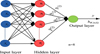 |
Fig. 1 Layers of ANN. |
While, the entire training set of m samples is defined in equation (2).![Mathematical equation: $$ J(W,b)=\left[\frac{1}{m}\sum_{i=1}^mJ(W,b;{x}^i,{y}^i)\right]+\frac{\lambda }{2}\sum_{l=1}^{{nl}-1}\sum_{i=1}^sl\sum_{j=1}^{{sl}=1}{\left({W}_{{ji}}^{(l)}\right)}^2 $$](/articles/stet/full_html/2025/01/stet20240415/stet20240415-eq2.gif) (2)
(2)
![Mathematical equation: $$ J(W,b)=\left[\frac{1}{m}\sum_{i=1}^m\left(\frac{1}{2}{||{hw},b{(x)}^{(i)})-{y}^{(i)}||}^2\right)\right]+\frac{\lambda }{2}\sum_{l=1}^{{nl}-1}\sum_{i=1}^sl\sum_{j=1}^{{sl}=1}{\left({W}_{{ji}}^{(l)}\right)}^2 $$](/articles/stet/full_html/2025/01/stet20240415/stet20240415-eq3.gif) (3)
(3)
where J(W, b) in equation (2) is an average sum of square error term, and equation (3) is the weight decay or regularization term that decreases the magnitude of the weight, and helps to prevent overfitting. Also, λ is the weight decay parameter. The linear aggregator is simply the summation (Σ) that combines all the incoming signals (X1, X2, …, Xn) with their corresponding weights (W1, W2, …, Wn). This weighted sum is then called the activation voltage. θ is the bias used to identify the suitable point that the linear aggregator makes. U denotes the activation potential. If this value is positive, then u ≥ θ, the model has an excitatory potential; otherwise, it will be inhibitory. g is the activation function, while y is the output signal [48, 49].
This clarifies that equation (4) defines the ANN output concept introduced by McCulloch and Pitts [50]. (4)
(4)
y = g(u). Therefore, ANNs process information by mimicking the brain. They take input signals, like fault currents, multiply them by learned weights, and sum them up. This creates an activation potential. An activation function then refines this value to influence the output, which reflects the input patterns the network has learned. This process allows ANNs to identify and classify faults effectively. The error of a neuron j in the output layer y is given in equation (5). (5)
(5)
where, Rj is predetermined value, and E is total error of the output layer as shown in equation (6)
 (6)
(6)
ANNs continuously improve by adjusting connections between weights as shown in equation (7). The delta rule helps them learn by calculating how much to adjust each weight (ΔWkj) based on the error (E) and a learning rate (α). This is similar to gradient descent, a common optimization technique. (7)
(7)
Backpropagation automatically adjusts the connections (weights) in an ANN based on the error. This fine-tuning, guided by the positive or negative gradient, helps the network learn complex patterns. This makes ANNs with backpropagation powerful for tasks like signal prediction and system modeling.
Figure 2 describes how the flow chart of an algorithm is executed from the data extraction to fault detection. This is achieved by proposed algorithm for ANN.
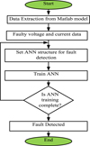 |
Fig. 2 Flow chart proposed algorithm for ANN. |
4 Adaptive neuro-fuzzy inference system
The ANFIS is an intelligent hybrid framework that integrates the adaptive learning capabilities of ANN with the human-like intellectual style of fuzzy logic systems. This synergy enables ANFIS to effectively model complex, non-linear systems and handle uncertainties. In ANFIS, the neural network component facilitates adaptive learning by adjusting the parameters of the fuzzy system based on input-output data, thereby enhancing the system’s accuracy and performance. Meanwhile, the fuzzy logic component provides a structured approach to approximate reasoning, allowing the system to make decisions based on imprecise or incomplete information. ANFIS is particularly valuable in applications where traditional methods fall short, such as in fault detection and classification in power systems, due to its capacity to learn from historical data and adapt to new patterns [51].
Fuzzification takes place in the input layer, sometimes referred to as Layer 1. In this instance, a membership value is assigned to each subset inside a fuzzy framework that serves as a discourse area for an input. For this problem, the mathematical simulation is given by equation (8). The several levels of the ANFIS algorithm are illustrated in Figure 3. (8)
(8)
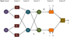 |
Fig. 3 Layers of ANFIS. |
The second layer, recognized as the fuzzy AND operation layer, is where each node performs the fuzzy AND operations by applying the algebraic result’s T-norm operator. The output result for every node is provided by equation (9). (9)
(9)
This layer is called the normalizing layer and it determines the result of the kth node by dividing the firing intensity of a particular rule by the total firing intensities of the entire rules in the fuzzy system in equation (10). Consequently, the beginning values of each fuzzy rule are normalized. (10)
(10)
Layer four is the part of the layer that has constant parameters. The function that every node k in this layer performs is shown in equation (11) as a linear product of its inputs, each of which is described by a set of variables that may be changed. (11)
(11)
Equation (12), single node aggregates all incoming inputs algebraically to form the network’s output at the output layer, also known as Layer 5. (12)
(12)
Figure 4 represents step-by-step algorithm of fault analysis using ANFIS.
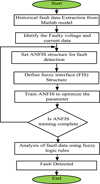 |
Fig. 4 Flow chart proposed algorithm for ANFIS. |
The ANFIS technique combines fuzzy logic and neural networks to model relationships in data. Below is the algorithm described mathematically with equations representing each step:
Step 1: Pre-processing data
1. Historical fault data X = {x1, x2, … … …, xn} is collected in equation (13), where xi,norm represents a vector of input parameters such as voltage, current, and phase information. (13)
(13)
2. Remove noise using filtering techniques (e.g., moving average or Gaussian filter).
Step 2: Feature extraction
Identify key feature F = {F1, F2, … … …, Fm} relevant to fault detection. These features include:
Equation (14) represents voltage dips: (14)
(14)
Equation (15) represents current surge: (15)
(15)
Phase angle in equation (16)
 (16)
(16)
The feature set becomes input to ANFIS model:
Step 3: Fuzzy Inference System (FIS) definition
1. Input: F = {F1, F2, … … …, Fm}.
2. Equation (17) defines membership function: Define membership function μ(fj) for each feature fj: (17)
(17)
For a triangular membership function.
3. Output variable: Defined output y for fault classification or location.
4. Rules: Initialize fuzzy rules: Rk: IF f1 is  AND f2 is
  THEN y = Bk.
Where  and Bk are fuzzy sets.
Step 4: ANFIS training
1. In equation (18), calculate rule firing strength: (18)
(18)
2. In equation (19), normalize firing strength: (19)
(19)
3. Output for each rule from equation (20): (20)where pk, qk, rk are parameters.
4. Total output in equation (21): (21)
(21)
5. Update parameters {pk, qk, rk} using backpropagation and least square error minimization.
Step 5: Fault detection
Input normalized features F into the trained ANFIS model.
The model detects faults if output y satisfies a predefined condition represented by equation (22): (22)
(22)
Step 6: Fault classification
Classify fault types FT using fuzzy logic rules based on input features as shown in equation (23): (23)
(23)
Step 7: Fault location
Estimation fault location Lf using the correlation between features and locations in equation (24): (24)where f(·) is a function derived from training the ANFIS model to map feature to fault location.
Step 8: Model validation
Validate the trained model using a separate dataset Dval:
Compute performance metrics in equation (25): (25)
(25)
Evaluate accuracy, precision, and recall to ensure robustness. This mathematical formulation ensures the ANFIS algorithm is represented concisely while covering all steps.
5 Proposed 11 kV transmission model
The study focused on fault identification and classification within a power system model, which was conducted using a MATLAB simulation. This simulation emphasized transient signal analysis in an overhead distribution system with a radial configuration extending over 10 km represented in Figure 5. The simulated system included an 11 kV/0.4 kV transformer with a capacity of 1 MVA. It featured tapped loads consuming 1,000,000 watts of active power and 100 VAR of reactive power. The system was powered by an 11 kV, 30 MVA, 50 Hz power supply, with an additional power source connected to another 11 kV bus, representing a realistic power distribution network with multiple sources. To evaluate the system’s performance under fault conditions, various fault scenarios were simulated at different locations within the system. These faults were characterized by their phases and fault resistances, which included a fault resistance Rf = 0.01 Ω, ground resistance Rg = 0.01 Ω, and a snubber resistance of 1 × 1 e6 Ω. The simulation explored different fault types, including Single Line-to-Ground (S-L-G), Line-to-Line-to-Ground (L-L-G), Line-to-Line-to-Line-to-Ground (L-L-L-G), and balanced three-phase faults. The inclusion of varying fault resistances allow for a comprehensive assessment of fault behavior under different conditions [52, 53].
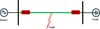 |
Fig. 5 A 11 kV three phase 10 km transmission line model |
The system parameters incorporated a generator source with an X/R ratio of 0.01, which is critical for analyzing fault current characteristics. Additionally, Table 1 provides essential details about the line parameters, specifically the zero and positive sequence impedances, which are key to understanding the system’s fault response and impedance characteristics. These parameters are vital for accurately modeling and diagnosing faults within the power system. This detailed setup provided a robust framework for identifying and classifying faults, enabling the analysis of their impact on the power distribution network.
Transmission line parameters.
Table 1 lists the model’s parameters: Resistances: R1 and R2 are positive and negative sequence for phases 1 and 2 and R0 is zero sequence; Inductances: L1, L2, L3 are positive and negative sequence for phases 1, 2, 3 and L0 is zero sequence; Capacitances: C1, C2, C3 are positive and negative sequence for phases 1, 2, 3 and C0 is zero sequence.
6 Fault type classification
The various types of faults are represented in Table 2. It provides a categorization of various types of electrical faults that can happen in a power system, along with their specific descriptions, essential for diagnosing and managing faults effectively to ensure system stability and reliability. Each fault type represents a different scenario of electrical disturbance, with single line-to-ground faults being the most common and typically easiest to detect and rectify, while double line-to-ground and line-to-line faults are more severe and can cause significant disruptions. Three-phase faults are the most severe, potentially leading to major power outages and equipment damage [54, 55]. This classification aids in designing protective relays and fault management systems, ensuring quick and accurate identification and resolution of faults to maintain system stability and prevent extensive damage.
Type of faults.
6.1 Fault detection using ANFIS
Fault detection is the initial and crucial step in power system fault management, where the presence of a fault is identified. Both ANN and ANFIS enhance this process by utilizing its neural network component to learn from historical fault data, continuously improving its ability to detect anomalies. The fuzzy logic aspect allows ANFIS to handle the uncertainties and non-linear characteristics of power system data effectively. By integrating these two technologies, ANFIS can accurately detect faults in real-time, significantly reducing the risk of undetected faults and ensuring the prompt initiation of corrective measures.
6.2 Fault classification using ANN and ANFIS
Once a fault is detected, it is essential to classify its type to determine the appropriate response. ANN and ANFIS excels in fault classification by leveraging its adaptive learning capability to distinguish between different fault types, such as line-to-ground, line-to-line, and three-phase faults. The neural network component learns the distinctive patterns of each fault type from the training data, while the fuzzy logic rules apply these patterns to classify new faults accurately. This combination ensures high classification accuracy, enabling system operators to deploy targeted and effective remedial actions.
6.3 Fault location using ANN and ANFIS
Identifying the precise location of a fault is vital for quick restoration of the power system. ANFIS aids in fault location by analyzing the fault data and estimating the distance to the fault point within the network. The neural network part of ANFIS processes historical data to understand the correlation between fault characteristics and their locations, while the fuzzy logic rules interpret this information to pinpoint the fault’s position accurately. This method decreases the time and attempt required for fault location, minimizing downtime and improving the overall reliability of the power system.
7 Simulation results and discussions
The Simulation of this work is carried out MATLAB/Simulink with bus capacity of 11 KV, 30 MVA Feeder, here the distance of the transmission line is considered as 10 km. The ANN and ANFIS models collect the data of RMS voltage, current and zero sequence component of the bus and generate the location accurately of the occurrence of the fault. Consider ABG fault is created at 0.1 s. Data is collected using the ANN and ANFIS models, which will detect, classify, and locate the fault as discussed below.
Figure 6 represents the collection of input data from the bus for fault classification. It has eight inputs, the first three is the RMS voltage of the bus and the next three will be the current of the bus. Layers 7 and 8 will be the zero-sequence components of the bus. The collection of the input data for locating fault was represented in Figure 7. It has three inputs, it receives the RMS voltage of the bus. Hence the fault distance will be calculated accordingly.
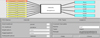 |
Fig. 6 Collection of input bus data for fault classification using ANFIS. |
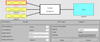 |
Fig. 7 Collection of input bus data for fault location using ANFIS. |
To analyze the detailed changes in the waveforms and fault detection system:
Voltage and current waveforms: At 0.1 s, a significant change occurs in both voltage and current waveforms. In voltage waveform, there is a sudden drop in the red and blue phase voltages, while the green phase voltage maintains its sinusoidal pattern, indicating a potential fault involving two phases. In current waveform, correspondingly, a sharp rise in the red and blue phase currents occurs, which reflects a high fault current due to the fault.
Fault detection output: The fault detector changes from 0 (no fault) to 1 (fault) at 0.1 s, indicating the exact moment the fault is detected by the system. The detection lasts until approximately 0.12 s, suggesting the fault is transient and resolves shortly thereafter.
Effect on the system: During the fault period (0.1–0.12 s), the system experiences high fault currents and voltage imbalances, which can:
-
Cause stress on the equipment, such as transformers and circuit breakers.
-
Lead to overheating or damage if not quickly cleared.
-
Affect downstream loads due to voltage dips, potentially causing disruptions.
Change due to fault: The fault likely originates from a phase-to-phase or phase-to-ground fault, as inferred from the behavior of voltage and current. Fault clearance at approximately 0.12 s might result from the action of a protection device, such as a circuit breaker, which isolates the faulted section to restore system stability.
System impact: The transient fault creates a ripple effect across the system, leading to fluctuations in power quality and possible downstream disruptions. Accurate detection and swift response, as demonstrated in the waveform, are critical for minimizing the duration and impact of the fault. This analysis highlights the importance of precise fault detection systems to ensure reliability and safety in power system operation.
The instantaneous parameters of the bus are represented in Figures 8 and 9 for ANFIS and ANN, where the fault detector indicates that the fault has occurred at 0.1 s and 0.11 s, respectively. The 0 and 1 conditions of the fault detector indicates the detection of the fault in the system. The RMS voltage and current of the bus by ANFIS are depicted in Figure 10.
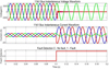 |
Fig. 8 Instantaneous voltage and current waveform of bus for ANFIS. |
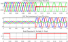 |
Fig. 9 Instantaneous voltage and current waveform of bus for ANN. |
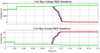 |
Fig. 10 RMS voltage and current waveform by ANFIS. |
The zero-sequence voltage and current of the bus, is illustrated in Figure 11, are crucial parameters calculated by the ANFIS model for the classification of faults within the power system. These zero-sequence parameters provide essential information about the asymmetrical components of the fault currents and voltages, which are pivotal in identifying and classifying the nature of the faults accurately. In the specific scenario of a double line-to-ground fault, represented as an ABG fault, the ANFIS model utilizes these zero-sequence parameters to distinguish the fault type. Figure 12 vividly displays the fault classification results, clearly indicating the occurrence of the ABG fault in the system. This classification is vital because it enables the system to take appropriate corrective measures tailored to the specific type of fault, thereby enhancing the overall fault management and system reliability. The ANFIS model, by processing these parameters, ensures that even subtle changes in the system’s electrical characteristics are accurately detected and classified. This leads to a more responsive and precise fault management system capable of minimizing the impact of faults and maintaining the stability of the power system.
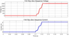 |
Fig. 11 Zero-sequence voltage and current of the bus. |
 |
Fig. 12 Classification of fault using ANFIS. |
The fault location identified by using ANFIS and ANN is presented in Figures 13a and 13b. The location of the fault is identified near 2.12 km by ANFIS, and the location of fault is identified near 2.2 km by ANN technique, which is accurate. Hence, the proposed ANFIS model detects, classifies, and locates the faults more accurately than ANN technique.
 |
Fig. 13 a) Location of fault using ANFIS. b) Location of fault using ANN. |
Differences between ANFIS and ANN based on their performance metrics and results in a fault detection and classification study. The ANFIS-based fault location results include the type of fault, actual fault distance (km), estimated fault location point (km), and percentage error, as shown in Table 3. The ANN-based fault location results include the type of fault, actual fault distance (km), estimated fault location point (km), and percentage error as shown in Table 4.
Fault location analysis for different types of faults based on ANFIS.
Fault location analysis for different type of faults based on ANN.
Differences between ANN and ANFIS based on their performance metrics and results in a fault detection and classification study. Table 5 focuses on the key differences between ANN and ANFIS models. It also highlights the importance of considering the specific context when choosing between these two techniques.
Comparative analysis between ANN and ANFIS.
Figures 14–18 illustrate five fault scenarios single-phase-to-ground fault, double line fault, double line-to-ground fault, three-phase fault, and three-phase-to-ground fault. Fault current and voltage data from these scenarios were used to train a machine-learning model for fault classification and localization. A significant current surge is evident in all fault conditions, as depicted in Figures 14–18, while Figure 18 specifically shows a complete voltage collapse, confirming a transmission line failure.
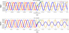 |
Fig. 14 a) Single line-to-ground fault (a-g) voltage. b) Single line-to-ground fault (a-g) current. |
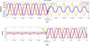 |
Fig. 15 a) Doubled line fault (a-b) voltage. b) Doubled line fault (a-b) current. |
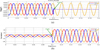 |
Fig. 16 a) Double line-to-ground fault (a-b-g) voltage. b) Double line-to-ground fault (a-b-g) current. |
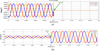 |
Fig. 17 a) Triple line fault (a-b-c) voltage. b) Triple line fault (a-b-c) current. |
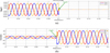 |
Fig. 18 a) Triple line-to-ground fault (a-b-c-g) voltage. b) Triple line-to-ground fault (a-b-c-g) current. |
Figure 14–18 clearly demonstrate the occurrence of abnormalities on the transmission line. A minimum fault resistance of 0.01 was established to enable the model to detect transient faults. Increasing this value diminishes fault detection capabilities, potentially generating inaccurate data that can adversely impact electrical installations. As illustrated in Figures 18a and 18b, where the voltage remains constant while current surges, such erroneous data can lead to system instability.
7.1. Validation of proposed technique using hardware prototype
Figure 19 depicts a real-time power electronics laboratory setup. It shows a user interface PC (Host RT Lab command station) connected to an OPAL-RT real-time simulator (op5600). This simulator is likely used to model and simulate power electronic systems. The user interface PC allows the user to control and monitor the simulation. An RT-Lab target PC is also connected, which could be used to implement real-time control algorithms or to interface with hardware in the loop. A DSO (Digital Storage Oscilloscope) is present to capture and analyze signals from the simulation or hardware. The setup likely involves a combination of hardware and software tools for research, development, and testing of power electronic systems.
 |
Fig. 19 Experimental setup workbench. |
Figure 20 illustrates a waveform analysis from an oscilloscope display showing the detection and termination of a fault in an electrical system. The top waveform (Va) represents the voltage signal (scaled at 600 A/div), while the bottom waveform (Ia) shows the current signal (scaled at 2 A/div). At the marked point “Fault detected,” there is a noticeable disturbance in the waveforms, indicating the onset of a fault condition. Subsequently, the system stabilizes, and normal waveform patterns are restored at the marked point “Fault terminated,” indicating the fault was cleared. The time base is set at 2 s per division, allowing for a clear visualization of the fault’s duration and system response. The results show the configuration settings of a DSO. It displays information about the channels connected to the DSO, including their labels, coupling (DC), voltage/division (V/div) settings, bandwidth, and vertical position. The DSO is currently set to display signals from channels 1, 2, 3_1, 3_2, 4_1, and 4_2. The time/division (Time/div) setting is 2 s/div, indicating that each horizontal division on the screen represents 2 s. The record length is set to 10 k samples, and the sample rate is 500 S/s. The trigger settings are not visible in the image.
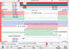 |
Fig. 20 L-L fault with ANFIS fault detection. |
The single line to ground fault accurately detection, classification, and location identification is illustrated in Figure 21, which exhibits the increase in the fault current and decrease in voltage at the fault.
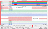 |
Fig. 21 S-L-G fault with ANFIS fault detection. |
Figure 22 exhibits that the voltage varies from normal to minimum value and current varies from normal to maximum current value for the line-line fault.
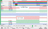 |
Fig. 22 L-L fault voltage and current with ANN fault detection. |
Figure 23 exhibits that current varies from normal value to higher value at the time triple line fault. Figure 23 shows the voltage (Va) and current (Ia) waveforms during a triple line fault in a power system. The sudden drop in voltage and the high-frequency oscillations in both voltage and current are characteristic of this type of fault. The fault causes a significant disturbance in the system, leading to voltage imbalance and increased current flow, which can potentially damage equipment if not mitigated quickly.
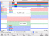 |
Fig. 23 L-L fault voltage and current with ANN fault detection. |
8 Conclusion
In conclusion, ANFIS- and ANN-based fault detection, classification, and location have effectively showcased the capabilities of an ANFIS and ANN model in managing faults within a power system. This study meticulously examined an ABG double line-to-ground fault scenario, where the ANFIS model exhibited a high degree of precision in detecting, classifying, and locating the fault than ANN. The ANFIS model’s fault detection mechanism accurately identified the occurrence of the fault, highlighting its sensitivity to anomalies within the power system. Following detection, the system’s classification capabilities were tested, and the model successfully categorized the fault as an ABG double line-to-ground fault. This classification is critical as it informs the necessary remedial actions and system responses to maintain stability and prevent further damage. Furthermore, the ANFIS and ANN model demonstrated exceptional accuracy in fault location, pinpointing the fault at approximately 2.12 km and 2.2 km from the reference point. This precise localization is instrumental in expediting the maintenance process, minimizing downtime, and ensuring prompt restoration of normal operations. The study’s findings underscore the reliability and robustness of ANFIS in fault management, contributing significantly to the operational efficiency and reliability of power systems. The research highlights the potential of ANFIS-based techniques as a vital tool for modern power system fault diagnostics, offering a sophisticated solution that enhances fault detection, classification, and localization processes.
References
- Wong J.Y.R., Tan C.K., Bakar A.H.A., Che H.S. (2022) Selectivity problem in adaptive overcurrent protection for microgrid with inverter-based distributed generators (IBDG): theoretical investigation and HIL verification, IEEE Trans. Power Deliv. 37, 4, 3313–3324. https://doi.org/10.1109/TPWRD.2021.3126897. [CrossRef] [Google Scholar]
- Xia B., Wang Y., Vazquez E., Xu W., Wong D., Tong M. (2015) Estimation of fault resistance using fault record data, IEEE Trans. Power Deliv. 30, 1, 153–160. https://doi.org/10.1109/TPWRD.2014.2355041. [CrossRef] [Google Scholar]
- Tabassum S., Vijay Babu A.R., Dheer D.K. (2023) Hybrid smart microgrid system modelling, design and control using an adaptive neuro fuzzy inference system, in: 2023 3rd International Conference on Emerging Frontiers in Electrical and Electronic Technologies (ICEFEET), Patna, India, 21–22 December, IEEE, pp. 1–6. https://doi.org/10.1109/ICEFEET59656.2023.10452232. [Google Scholar]
- Enríquez A.C., Cardoso Y.G., Martínez J.T. (2021) Microgrid protection, in: Anvari-Moghaddam A., Abdi H., Mohammadi-Ivatloo B., Hatziargyriou N. (eds), Microgrids: power systems, Springer, Cham, pp. 437–487. https://doi.org/10.1007/978-3-030-59750-4_17. [CrossRef] [Google Scholar]
- Tabassum S., Vijay Babu A.R., Dheer D.K. (2024) Real-time power quality enhancement in smart grids through IoT and adaptive neuro-fuzzy systems, Sci. Technol. Energy Transit. 79, 89. https://doi.org/10.2516/stet/2024085. [CrossRef] [Google Scholar]
- Tabassum S., Vijay Babu A.R., Dheer D.K., Pasha M.M. (2022) Inspection and surveillance of energy consumption in IoT-smart grid using wireless sensor network, in: 2022 IEEE 6th International Conference on Condition Assessment Techniques in Electrical Systems (CATCON 2022), Durgapur, India, 17–19 December, IEEE, pp. 308–312. https://doi.org/10.1109/CATCON56237.2022.10077673. [Google Scholar]
- Kanwal S., Jiriwibhakorn S. (2024) Advanced fault detection, classification, and localization in transmission lines: a comparative study of ANFIS, neural networks, and hybrid methods, IEEE Access 12, 49017–49033. https://doi.org/10.1109/ACCESS.2024.3384761. [Google Scholar]
- Al Kazzaz S.A.S., Ismael I., Mohammed K.K. (2020) Fault detection and location of power transmission lines using intelligent distance relay, Int. J. Power Electron. Drive Syst. 11, 2, 726–734. https://doi.org/10.11591/ijpeds.v11.i2.pp726-734. [CrossRef] [Google Scholar]
- Yuan C., Lai K., Illindala M.S., Haj-Ahmed M.A., Khalsa A.S. (2017) Multilayered protection strategy for developing community microgrids in village distribution systems, IEEE Trans. Power Deliv. 32, 1, 495–503. https://doi.org/10.1109/TPWRD.2016.2544923. [CrossRef] [Google Scholar]
- Narasipuram R.P., Mopidevi S. (2024) Assessment of E-mode GaN technology, practical power loss, and efficiency modelling of iL2C resonant DC-DC converter for xEV charging applications, J. Energy Storage 91, 112008. https://doi.org/10.1016/j.est.2024.112008. [CrossRef] [Google Scholar]
- Rao T.C.S., Ram S.S.T., Subrahmanyam J.B.V. (2017) An effective technique for fault detection and classification in distribution system with the aid of DWT and ANFIS, Int. J. Autom. Control 11, 4, 411–427. https://doi.org/10.1504/IJAAC.2017.087055. [CrossRef] [Google Scholar]
- Tabassum S., Vijay Babu A.R., Dheer D.K., Rui-Ming F.F., Liao Q.Q. (2024) A comprehensive exploration of IoT-enabled smart grid systems: power quality issues, solutions, and challenges, Sci. Technol. Energy Transit. 79, 62. https://doi.org/10.2516/stet/2024056. [CrossRef] [Google Scholar]
- Elbaset A.A., Hiyama T. (2009) Fault detection and classification in transmission lines using ANFIS, IEEJ Trans. Ind. Appl. 129, 7, 705–713. https://doi.org/10.1541/ieejias.129.705. [CrossRef] [Google Scholar]
- Kumar P., Rao G., Babu A.R.V. (2020) A novel diagnostic technique to detect the failure mode operating states of an air-breathing fuel cell used in fuel cell vehicles, Int. J. Electr. Hybrid Veh. 12, 32–43. https://doi.org/10.1504/IJEHV.2020.10025991. [CrossRef] [Google Scholar]
- Khaleghi A., Oukati Sadegh M., Ghazizadeh-Ahsaee M., Mehdipour Rabori A. (2018) Transient fault area location and fault classification for distribution systems based on wavelet transform and adaptive neuro-fuzzy inference system (ANFIS), Adv. Electr. Electron. Eng. 16, 2, 155–166. https://doi.org/10.15598/aeee.v16i2.2563. [Google Scholar]
- Babu A.R.V., Rajyalakshmi V., Suresh K. (2017) Renewable energy integrated high gain DC-DC converter with multilevel inverter for water pumping applications, J. Adv. Res. Dyn. Control Syst. 1, 172–190. [Google Scholar]
- Babu A.R.V., Rao G., Kumar P., Saranu S., Babu A., Uma Ch., Rao M., Teja A.J.R. (2015) Energy and green house gas payback time analysis of an air breathing fuel cell stack, J. Electr. Eng. 15, 52–61. [Google Scholar]
- Saranya D.N.S., Babu A.R.V., Rao G., Tagore Y.R., Kumar N. (2015) Fuel cell powered bidirectional DC-DC converter with fuzzy logic controller for electric vehicle applications, Int. J. Appl. Eng. Res. 8, 109, 117–120. [Google Scholar]
- Hong Y.Y., Cabatac M.T.A.M. (2020) Fault detection, classification, and location by static switch in microgrids using wavelet transform and taguchi-based artificial neural network, IEEE Syst. J. 14, 2, 2725–2735. https://doi.org/10.1109/JSYST.2019.2925594. [CrossRef] [Google Scholar]
- Adefarati T., Bansal R.C. (2019) Reliability, economic and environmental analysis of a microgrid system in the presence of renewable energy resources, Appl. Energy 236, 1089–1114. https://doi.org/10.1016/j.apenergy.2018.12.050. [CrossRef] [Google Scholar]
- Tightiz L., Nasab M.A., Yang H., Addeh A. (2020) An intelligent system based on optimized ANFIS and association rules for power transformer fault diagnosis, ISA Trans. 103, 63–74. https://doi.org/10.1016/j.isatra.2020.03.022. [CrossRef] [Google Scholar]
- Lin H., Sun K., Tan Z.H., Liu C., Guerrero J.M., Vasquez J.C. (2019) Adaptive protection combined with machine learning for microgrids, IET Gener. Transm. Distrib. 13, 6, 770–779. https://doi.org/10.1049/iet-gtd.2018.6230. [CrossRef] [Google Scholar]
- Meng X., Zhang B., Cao F., Liao Y. (2024) Effectiveness of measures on natural gas pipelines for mitigating the influence of DC ground current, IEEE Trans. Power Deliv. 39, 4, 2414–2423. https://doi.org/10.1109/TPWRD.2024.3406826. [CrossRef] [Google Scholar]
- Liu K., Jiao S., Nie G., Ma H., Bo G., Sun C., Xin D., Saha T., Wu G. (2024) On image transformation for partial discharge source identification in vehicle cable terminals of high‐speed trains, High Voltage 9, 1090–1100. https://doi.org/10.1049/hve2.12487. [CrossRef] [Google Scholar]
- Cheng C., Deng X., Zhao X., Xiong Y., Zhang Y. (2023) Multi-occupant dynamic thermal comfort monitoring robot system, Build. Environ. 234, 110137. https://doi.org/10.1016/j.buildenv.2023.110137. [CrossRef] [Google Scholar]
- Jiang W., Zheng B., Sheng D., Li X. (2024) A compensation approach for magnetic encoder error based on improved deep belief network algorithm, Sensors Actuators A. Phys. 366, 115003. https://doi.org/10.1016/j.sna.2023.115003. [CrossRef] [Google Scholar]
- Lu Y., Wang S., Zhang C., Chen R., Dui H., Mu R. (2024) Adaptive maintenance window-based opportunistic maintenance optimization considering operational reliability and cost, Reliab. Eng. Syst. Saf. 250, 110292. https://doi.org/10.1016/j.ress.2024.110292. [CrossRef] [Google Scholar]
- Field A.D., Attention I.D., Network R. (2024) Intelligent fault diagnosis of rolling bearing based on Gramian angular difference field and improved dual attention, Sensors 24, 7, 2156. https://doi.org/10.3390/s24072156. [CrossRef] [PubMed] [Google Scholar]
- Ju X., Jiang Y., Jing L., Liu P. (2023) Quantized predefined-time control for heavy-lift launch vehicles under actuator faults and rate gyro malfunctions, ISA Trans. 138, 133–150. https://doi.org/10.1016/j.isatra.2023.02.022. [CrossRef] [Google Scholar]
- Wang Q., Chen L., Xiao G., Wang P., Gu Y., Lu J. (2024) Elevator fault diagnosis based on digital twin and PINNs-e-RGCN, Sci. Rep. 14, 30713. https://doi.org/10.1038/s41598-024-78784-7. [CrossRef] [Google Scholar]
- Zhang R., Wang S., Ma J., Jiang Y., Wang P., Liu T., Yang Y. (2024) An asymmetric hybrid phase-leg modular multilevel converter with small volume, low cost, and DC fault-blocking capability, IEEE Trans. Power Electron. 40, 5336–5351. https://doi.org/10.1109/TPEL.2024.3510792. [Google Scholar]
- Zhang J., Feng X., Zhou J., Zang J., Wang J., Shi G. (2023) Series – shunt multiport soft normally open points, IEEE Trans. Ind. Electron. 70, 11, 10811–10821. https://doi.org/10.1109/TIE.2022.3229375. [CrossRef] [Google Scholar]
- Sun J., Wang L., Li J., Li F., Fang Y. (2024) An on-line imaging sensor based on magnetic deposition and flowing dispersion for wear debris feature monitoring, Mech. Syst. Signal Process. 212, 111321. https://doi.org/10.1016/j.ymssp.2024.111321. [CrossRef] [Google Scholar]
- Miaofen L., Youmin L., Tianyang W., Chu F., Peng Z.K. (2023) Adaptive synchronous demodulation transform with application to analyzing multicomponent signals for machinery fault diagnostics, Mech. Syst. Signal Process. 191, 110208. https://doi.org/10.1016/j.ymssp.2023.110208. [CrossRef] [Google Scholar]
- Hang J., Wang X., Li W., Ding S. (2025) Interturn short-circuit fault diagnosis and fault-tolerant control of DTP-PMSM based on subspace current residuals, IEEE Trans. Power Electron. 40, 2, 3395–3404. https://doi.org/10.1109/TPEL.2024.3484469. [CrossRef] [Google Scholar]
- Hang J., Qiu G., Hao M., Ding S. (2024) Improved fault diagnosis method for permanent magnet synchronous machine system based on lightweight multi-source information data layer fusion, IEEE Trans. Power Electron. 39, 13808–13817. https://doi.org/10.1109/TPEL.2024.3432163. [CrossRef] [Google Scholar]
- Ni L., Chen J., Chen G., Zhao D., Wang G., Aphale S. (2024) An explainable neural network integrating Jiles-Atherton and nonlinear auto-regressive exogenous models for modeling universal hysteresis, Eng. Appl. Artif. Intell. 136, 108904. https://doi.org/10.1016/j.engappai.2024.108904. [CrossRef] [Google Scholar]
- Fan H., Wang C., Li S. (2024) Computer methods in applied mechanics and engineering novel method for reliability optimization design based on rough set theory and hybrid surrogate model, Comput. Methods Appl. Mech. Eng. 429, 117170. https://doi.org/10.1016/j.cma.2024.117170. [CrossRef] [Google Scholar]
- Zhang H., Chen Z., Yu C., Yue D., Xie X., Hancke G. (2024) Event-trigger-based resilient distributed energy management against FDI and DoS attack of cyber–physical system of smart grid, IEEE Trans. Syst. Man Cybern. Syst. 54, 3220–3230. https://doi.org/10.1109/TSMC.2024.3357497. [CrossRef] [Google Scholar]
- Zhi S., Shen H., Wang T. (2024) Gearbox localized fault detection based on meshing frequency modulation analysis, Appl. Acoust. 219: 109943. https://doi.org/10.1016/j.apacoust.2024.109943. [CrossRef] [Google Scholar]
- Hu X., Tang T., Tan L., Zhang H. (2023) Fault detection for point machines: a review, challenges, and perspectives, Actuators 12, 10, 391. https://doi.org/10.3390/act12100391. [CrossRef] [Google Scholar]
- Lin L., Ma X., Chen C., Xu J., Huang N. (2024) Imbalanced industrial load identification based on optimized CatBoost with entropy features, J. Electr. Eng. Technol. 19, 1–16. https://doi.org/10.1007/s42835-024-01933-5. [CrossRef] [Google Scholar]
- Huang Z., Zhang C., Ge L., Chen Z., Lu K., Wu C. (2024) Joining spatial deformable convolution and a dense feature pyramid for surface defect detection, IEEE Trans. Instrum. Meas. 73, 5012614. https://doi.org/10.1109/TIM.2024.3370962. [Google Scholar]
- Qiao Y., Lu J., Wang T., Liu K., Zhang B., Snoussi H. (2023) A multihead attention self-supervised representation model for industrial sensors anomaly detection, IEEE Trans. Ind. Inform. 20, 2190–2199. https://doi.org/10.1109/TII.2023.3280337. [Google Scholar]
- Rong Q., Hu P., Yu Y., Wang D., Cao Y., Xin H. (2024) Virtual External perturbance-based impedance measurement of grid-connected converter, IEEE Trans. Ind. Inform. 72, 2644–2654. https://doi.org/10.1109/TIE.2024.3436629. [Google Scholar]
- Rong Q., Hu P., Wang L., Li Y., Yu Y., Wang D., Cao Y. (2024) Asymmetric sampling disturbance-based universal impedance measurement method for converters, IEEE Trans. Power Electron. 39, 15457–15461. https://doi.org/10.1109/TPEL.2024.3451403. [CrossRef] [Google Scholar]
- Meng X., Lin L., Li H., Chen Y., Mei H. (2024) Characteristics of streamer discharge along the insulation surface with embedded electrode, IEEE Trans. Dielectr. Electr. Insul. 31, 2038–2044. https://doi.org/10.1109/TDEI.2024.3394833. [CrossRef] [Google Scholar]
- Zhi S., Wu H., Shen H., Wang T., Fu H. (2024) Entropy-aided meshing-order modulation analysis for wind turbine planetary gear weak fault detection under variable rotational speed, Entropy 26, 5, 409. https://doi.org/10.3390/e26050409. [CrossRef] [PubMed] [Google Scholar]
- Zhang J., Li H., Kong X., Zhou J., Shi G., Zang J., Wang J. (2024) A novel multiple-medium-AC-port power electronic transformer, IEEE Trans. Ind. Electron. 71, 7, 6568–6578. https://doi.org/10.1109/TIE.2023.3301550. [CrossRef] [Google Scholar]
- McCulloch W.S., Pitts W. (1943) A logical calculus of the ideas immanent in nervous activity, Bull. Math. Biophys. 5, 4, 115–133. https://doi.org/10.1007/BF02478259. [CrossRef] [Google Scholar]
- Zhang H., Yu C., Zeng M., Ye T., Yue D., Dou C., Xie X., Hancke G.P. (2024) Homomorphic encryption-based resilient distributed energy management under cyber-attack of micro-grid with event-triggered mechanism, IEEE Trans. Smart Grid 15, 5, 5115–5126. https://doi.org/10.1109/TSG.2024.3390108. [CrossRef] [Google Scholar]
- Lin L., Liu J., Huang N., Li S., Zhang Y. (2024) Multiscale spatio-temporal feature fusion based non-intrusive appliance load monitoring for multiple industrial industries, Appl. Soft Comput. 167, 112445. https://doi.org/10.1016/j.asoc.2024.112445. [CrossRef] [Google Scholar]
- Wang H., Zhou Z., Xu Z., Ge X., Yang Y., Zhang Y., Yao B., Xie D. (2024) A thermal network model for multichip power modules enabling to characterize the thermal coupling effects, IEEE Trans. Power Electron. 39, 5, 6225–6245. https://doi.org/10.1109/TPEL.2024.3355207. [CrossRef] [Google Scholar]
- Li T., Shi H., Bai X., Li N., Zhang K. (2025) Rolling bearing performance assessment with degradation twin modeling considering interdependent fault evolution, Mech. Syst. Signal Process. 224, 112194. https://doi.org/10.1016/j.ymssp.2024.112194. [CrossRef] [Google Scholar]
- Liu K., Jiao S., Nie G., Ma H., Gao B., Sun C., Xin D., Saha T.K., Wu G. (2024) On image transformation for partial discharge source identification in vehicle cable terminals of high-speed trains, High Voltage 9, 5, 1090–1100. https://doi.org/10.1049/hve2.12487. [CrossRef] [Google Scholar]
All Tables
All Figures
|
Fig. 1 Layers of ANN. |
| In the text | |
|
Fig. 2 Flow chart proposed algorithm for ANN. |
| In the text | |
|
Fig. 3 Layers of ANFIS. |
| In the text | |
|
Fig. 4 Flow chart proposed algorithm for ANFIS. |
| In the text | |
|
Fig. 5 A 11 kV three phase 10 km transmission line model |
| In the text | |
|
Fig. 6 Collection of input bus data for fault classification using ANFIS. |
| In the text | |
|
Fig. 7 Collection of input bus data for fault location using ANFIS. |
| In the text | |
|
Fig. 8 Instantaneous voltage and current waveform of bus for ANFIS. |
| In the text | |
|
Fig. 9 Instantaneous voltage and current waveform of bus for ANN. |
| In the text | |
|
Fig. 10 RMS voltage and current waveform by ANFIS. |
| In the text | |
|
Fig. 11 Zero-sequence voltage and current of the bus. |
| In the text | |
|
Fig. 12 Classification of fault using ANFIS. |
| In the text | |
|
Fig. 13 a) Location of fault using ANFIS. b) Location of fault using ANN. |
| In the text | |
|
Fig. 14 a) Single line-to-ground fault (a-g) voltage. b) Single line-to-ground fault (a-g) current. |
| In the text | |
|
Fig. 15 a) Doubled line fault (a-b) voltage. b) Doubled line fault (a-b) current. |
| In the text | |
|
Fig. 16 a) Double line-to-ground fault (a-b-g) voltage. b) Double line-to-ground fault (a-b-g) current. |
| In the text | |
|
Fig. 17 a) Triple line fault (a-b-c) voltage. b) Triple line fault (a-b-c) current. |
| In the text | |
|
Fig. 18 a) Triple line-to-ground fault (a-b-c-g) voltage. b) Triple line-to-ground fault (a-b-c-g) current. |
| In the text | |
|
Fig. 19 Experimental setup workbench. |
| In the text | |
|
Fig. 20 L-L fault with ANFIS fault detection. |
| In the text | |
|
Fig. 21 S-L-G fault with ANFIS fault detection. |
| In the text | |
|
Fig. 22 L-L fault voltage and current with ANN fault detection. |
| In the text | |
|
Fig. 23 L-L fault voltage and current with ANN fault detection. |
| In the text | |
Current usage metrics show cumulative count of Article Views (full-text article views including HTML views, PDF and ePub downloads, according to the available data) and Abstracts Views on Vision4Press platform.
Data correspond to usage on the plateform after 2015. The current usage metrics is available 48-96 hours after online publication and is updated daily on week days.
Initial download of the metrics may take a while.