")
")
| Issue |
Sci. Tech. Energ. Transition
Volume 78, 2023
|
|
|---|---|---|
| Article Number | 39 | |
| Number of page(s) | 18 | |
| DOI | https://doi.org/10.2516/stet/2023025 | |
| Published online | 22 December 2023 | |
Regular Article
Study on structural design and hydrodynamic response law of new floating wind power fishery integration
Department of Engineering Mechanics, School of Storage, Transportation and Architectural Engineering, China University of Petroleum (East China), Qingdao, Shandong 266580, China
* Corresponding author: This email address is being protected from spambots. You need JavaScript enabled to view it.
Received:
27
July
2022
Accepted:
29
August
2023
Abstract
The new lattice floating wind turbine integrated system (also known as Dot Matrix Floating wind turbine, and hereinafter referred to as DMF) is proposed as a new concept. It is a design scheme that combines multiple wind turbines into a polygonal floating foundation in the form of a lattice arrangement, which can meet the research and development requirements of higher power generation equipment in the future. More far-reaching, it has obvious advantages over the traditional floating wind turbine scheme in terms of structural cost and motion stability, which provides a new idea for the development of offshore wind power energy. Firstly, the structural parameters and mechanical model of DMF are analyzed to determine the feasibility and superiority of the overall scheme of the new lattice foundation. Combined with the traditional OC4 semi-submersible wind turbine system, the hydrodynamic simulation under wind, wave, and current load is carried out, and the hydrodynamic response law of DMF under the different environmental factors is summarized and analyzed. It is concluded that the stability of DMF in pitching motion is 70% higher than that of traditional OC4 system. In order to further verify the feasibility of the DMF system and the accuracy of the theoretical model, based on the similarity theory, this study carried out the small-scale prototype processing of DMF and the simulation experiment of wind wave flume. The test results are in good agreement with the simulation data. Finally, aiming at the problem of the large amplitude of swaying motion response of DMF in the simulation results, a mooring optimization scheme suitable for the new DMF is proposed, which provides 47% stability compared with the traditional catenary mooring through comparative analysis. This study provides a reference and theoretical basis for the research and development of offshore multi-wind turbine combined equipment and hydrodynamic stability optimization. It has certain theoretical guiding significance and economic development value.
Key words: Dot matrix / Multi-machine integration / Hydrodynamic response / Flume test / Stability optimization
© The Author(s), published by EDP Sciences, 2023
 This is an Open Access article distributed under the terms of the Creative Commons Attribution License (https://creativecommons.org/licenses/by/4.0), which permits unrestricted use, distribution, and reproduction in any medium, provided the original work is properly cited.
Nomenclature
DMF: Dot Matrix Floating wind turbine
VRW : Relative wind speed (m/s)
VS : Horizontal movement speed (m/s)
VW : Actual wind speed (m/s)
Cdn : Resistance coefficient of normal flow
Cdt : Tangential flow resistance coefficient
CM : Mass factor
Cd90 : Vertical angle of attack resistance coefficient
Cd0 : Horizontal angle of attack drag coefficient
CDC : Flow resistance coefficient
Sij : Area of waterline surface (m2)
RDi : Horizontal distance (m)
1 Introduction
Offshore floating wind turbines have better development prospects and wider applications than onshore wind turbines, so they are better used to generate electricity through floating wind turbines. With the continuous development and utilization of offshore energy technology, offshore floating wind turbines are increasingly moving towards the development direction of deep sea and high-power. At the same time, in terms of taking into account the structural safety and cost-effectiveness of wind turbines, the development of high-power and floating wind turbines in the deep-sea field has greater advantages and prospects.
The development of floating wind power structures mainly includes two modes. One is to continue to increase the blade size and tower height on the basis of the single wind turbine structure. The other is the combination of multiple wind turbines into a floating platform structure. At present, there are mainly some concepts and schemes in the related research of multi-wind turbines sharing a basic platform. Liu et al. [1, 2] put forward the concept of a semi-submersible integrated foundation with three wind turbines, and analyzed the hydrodynamic response law. It was concluded that there was a large difference in the motion response amplitude of the structure under the loads in different wind, wave, and current directions in 2021. Tethys et al. [3] established the Poseidon wind wave platform to generate 33 kW of wind energy in 2020. W2power by Pelagic Power is a semi-submersible triangular platform proposed to combine wind and wave power to meet the energy [4]. It has two or three wind turbines and can achieve a rated power of 10 MW. Zheng et al. [5] proposed the hex box concept to integrate fish farming with three 60 kW wind turbines. However, the scheme does not further show the results of experiment and field engineering application analysis. The multi-purpose wind turbine designed by Hexicon meets 10 MW power generation [6]. However, the hydrodynamic response stability of the triangular structure has not been further verified. Papandroulakis et al. [7] designed a fish aquaculture system. Zheng et al. [8] project to be integrated into a triangular floating platform with two 3.5 MW wind turbines. Power [9] has put forward the integrated conceptual design of 8 wind turbines according to the ocean hybrid platform, including the capacity of four 0.75 MW and four 6 kwp wind turbines. Figure 1 shows the concept that different wind turbine numbers share one basic platform. These multi-wind turbine integration concepts provide the foundation for high-power and large-scale power generation in the future. It is necessary to carry out further research on hydrodynamic response and mooring stability.
 |
Figure 1 Concept of multi-wind turbine integrated structure. |
There have been some research results on the structural characteristics and hydrodynamic laws of offshore wind power. Bulder et al. [10] used the linear frequency domain hydrodynamic method to explore the relationship between RAO (Response Amplitude Operator) and amplitude standard deviation of six degrees of freedom motion of a 5 MW three-floating foundation. Wayman et al. [11, 12] studied the dynamic response of various wind turbine foundations under different environmental loads. Sweetman et al. [13–15] applied the law of conservation of momentum to calculate the large-scale motion of a floating wind turbine platform in wind and waves. Nielsen et al. [16, 17] combined the aerodynamic follow-up elastic model HAWC2 with the simo/riflex program of the hydrodynamic module and the anchoring module, designed the Hywind spar floating foundation to support the 5 MW wind turbine, developed the relevant control system, and compared the calculation results with the results of the model test. Karimirad and Moan [18] and Matha et al. [19] calculated the dynamic response of the floating wind turbine under extreme sea conditions and the dynamic response of the structure. It provides a theoretical reference for the adaptability analysis of multi-wind turbine integrated floating structures under extreme wind, wave, and current environments. Matha et al. studied the dynamic response of a 5 MW tension leg floating wind turbine and compared the time domain results with the frequency domain results in order to better determine the adaptability of the structure under various environmental parameters. Adam et al. [20] proposed a new type of tension leg floating wind turbine in 2013 and conducted a 1:37 model test on it in the Marin pool in the Netherlands. In the test, the hydrodynamic effects of various sea conditions that may occur in the sea area to be installed on the model are considered.
To meet the demand for 30 MW high-power power generation, the design of a dot matrix hexagonal wind turbine foundation is based on the structural characteristics of traditional OC4 semi-submersible wind turbine platform and wind load platform in this study. Through the comparative analysis of numerical simulation and flume experiment, the feasibility and superiority of the overall scheme of the new lattice foundation are established. It provides a reference and theoretical basis for the research and development of offshore multi-wind turbine combined equipment and hydrodynamic stability optimization. It has certain theoretical guiding significance and economic development value.
2 Dot matrix polygon floating foundation
2.1 Main structure design
Conventional floating wind turbine foundations mainly include Spar platform, OC4 semi-submersible type, and TLP (Tension Leg Type). They are floating platforms that provide single wind turbines. Due to the large proportion of the main height of the wind turbine compared with the size of the platform, a large pitching motion is inevitable. With the development of offshore wind power to tens of megawatts and higher power, the blade size and tower height of wind turbines have exceeded 100 m, and the size of floating infrastructure has also developed to a larger scale. The safety, stability, and economic cost of this super large standing floating structure are also facing greater challenges. Therefore, this study proposes an innovative lattice polygon floating foundation. As shown in Figure 2. The floating foundation adopts a hexagonal structure frame, and six wind turbines are installed on six pontoons. This kind of dot matrix polygonal floating foundation can provide a large waterline surface moment of inertia and maintain good motion stability under the action of wind inclination moment. The DMF platform evenly distributes the self-weight and Wind float of the wind turbine to the pontoons at six corners, improves the load distribution of the overall floating structure, and provides the operation safety of the overall structure.
 |
Figure 2 Concept of dot matrix floating foundation. |
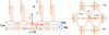 |
Figure 3 Dot matrix basic parameter model. |
The DMF platform design of this study refers to the traditional OC4 semi-submersible floating foundations, and the detailed parameters are shown in Table 1. In the design scheme of the six wind turbines in this paper, when the initial wind speed in the environment is 25 m/s, we study the design scheme of the integration of the six wind turbines in the new DMF (Dot Matrix Floating wind turbine). The front wind turbines can generate power at full capacity of 5 MW, while the rear wind turbines can generate power at 50% of the wind speed. The biggest difference between the parameters of a dot matrix foundation and a traditional semi-submersible floating foundation is the number and spacing of pontoons. In order to ensure the safe distance between lattice wind turbines and the overall strength of the structure, the pontoon spacing is set as 1.1 D wind turbine blade sweeping diameter.
Basic parameters of DMF structure.
2.2 Arrangement scheme of dot matrix wind turbine generator
Figure 2 shows the basic parameters of the dot matrix. Six NREL baseline 5 MW wind turbines are distributed on the six corner pontoons of the foundation in a dot matrix scheme. The pontoon size design principle is based on the maximum drainage volume that can be provided, and the buoyancy generated is greater than the gravity of the wind turbine and the pontoon itself. The arrangement position of dot matrix wind turbines shall be designed to ensure that all wind turbines can achieve normal rated power generation efficiency. The distribution of wind turbine wake is an important factor affecting the overall power generation and efficiency, and it is also an important reference for the arrangement spacing of multiple wind turbines. The research results of Takanori et al. [21–26] show that the wake velocity distribution of NREL-5MW [27] wind turbine is quite different in the X, Y, and Z axes.
The dot matrix arrangement scheme can form the mutual restriction between the six wind turbines, effectively balance the wind tilt moment between the wind turbines, and generate greater waterline inertia moment to balance the wind tilt moment, to reduce the pitching motion. The self-structure has better operation stability than the traditional semi-submersible. The lattice arrangement can better balance the load distribution and ensure the safety of the overall structure.
2.3 Mooring system layout scheme
Referring to the OC4 semi-submersible mooring system, DMF adopts the same three anchor chain line constraints for better comparative analysis. Figure 4 shows the arrangement of the mooring system. The mooring system consists of three identical anchor chain lines, and the included angle between any two adjacent catenary lines is 120 m. The distance between adjacent horizontal guide holes of the platform is designed to be 148 m, and the distance between the horizontal guide holes of the platform is 148 m, which is located at the center of the three guide holes. The other end of the mooring line is fixed at the seabed anchor point 200 m deep. The horizontal distance from the anchor point to the initial center of the platform is 837.6 m, and the initial length of the anchor line is 835.5 m.
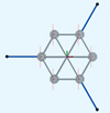 |
Figure 4 Mooring system layout scheme. |
Refer to the mooring system published by NREL and in combination with API RP 2SK [28] and DNV [29] specifications. We determine the mooring mode, wet weight, axial stiffness, mooring materials, mooring mode, and minimum breaking force of the new DMF structure.
3 Theoretical analysis
The coordinate position of the DMF floating foundation is shown in Figure 4. The coordinates are determined according to the right-hand coordinate criterion. The origin is selected on the water surface and intersects with the central axis of the tower support pontoon. The Z axis is vertical and upward and coincides with the central axis of the tower support pontoon. The whole model is symmetrical about the X-axis.
3.1 Load calculation
1) Wind float
Wind load is an important factor in the dynamic stability analysis of DMF. In order to facilitate the conduct of wave current pool tests, steady-state constant speed wind can be selected for the analysis of wind load. Calculate the wind load based on the maximum power during wind power generation. In the simulation and experiment conducted in this article, the obtained wind load thrust is directly applied equivalently to the structural model. In kinematic analysis, mooring analysis, and other analyses and calculations, wind usually needs to consider turbulence changes. Generally, the wind spectrum is used to describe the turbulence change of wind speed. Formula (1) shows that the SNPD(f) wind spectrum in API RP 2A [28, 29] represents the fluctuation of wind energy density. (1)
(1)
SNPD(f) is the spectral density of the wind spectrum, m2/s. z is the vertical height of sea level, m. f is the wind speed frequency, Hz. U10 is the average wind speed within 1 h at the reference height of 10 m, m/s. Based on the wind turbine wake non-rotating momentum theory, the ideal wind wheel momentum theory can be used to describe the relationship between the force acting on the wind wheel and the incoming flow velocity. The air velocity triangle on the blade element and the normal force acting on the blade element are calculated. Finally, the thrust, torque, and power of the wind turbine can be obtained according to the integration. The horizontal thrust formula between the wind turbine blade and the tower is established: (2)
(2)
 (3)
(3)
VRW is the relative wind speed, VRW = VW − VS, VW is the actual wind speed, VS is the horizontal movement speed of the floating wind power fishery structure in the downwind direction; CS is the shape coefficient, CH is the height coefficient, L is the height of the tower of the wind turbine, A is the wind direction of the blade vertical wind direction.
2) Wave load
The solution of wave loads in engineering is mostly based on Airy wave theory, and regular wave theory is used in model analysis. Specifically, it is assumed that waves are uniform, incompressible, and non viscous. The analysis method of wave loads is mainly based on the relationship between wavelength and characteristic length. The calculation method of wave frequency load is based on the characteristic scale D and wavelength of member section λ ratio, D(D/λ ≤ 0.2) is a small-scale component. According to Morison’s formula, the wave frequency load of structures such as net clothes and small components in this study is determined: (4)
(4)
In the formula,  is the drag force. Since the traditional Morrison formula is mainly used to calculate hydrodynamic fixed objects, the integrated structure of wind power fishery in this study is floating objects on the sea.
  is inertial force load. CD is the drag force coefficient. CI is the inertial force coefficient. u is the water quality point velocity, x is the component speed. When D/λ ≤ 0.2 is a small-scale component. The wave frequency load is calculated according to the Morison formula. When D/λ > 0.2 is a large-scale component. The wave frequency load is calculated according to the diffraction theory. The characteristic dimension of the new DMF overall structure is 300 m, D/λ = 1.5 is a large-scale component, and the wave frequency load is calculated according to the diffraction theory of Formula (5). When only a single structure is analyzed, the characteristic dimensions include pontoon diameter of 15 m, transverse brace diameter of 2 m, and central pontoon diameter of 8 m. D/λ = 0.075, 0.01, and 0.04 are small-scale components, and the wave frequency load is calculated according to Formula (6) Morison theory. The determination of the two theoretical calculation methods is mainly based on the relationship between the characteristic scale and the wavelength of the floating structure.
 (5)
(5)
In the formula, Cdn is the resistance coefficient of normal flow. Cdt is the tangential flow resistance coefficient. CM is the mass factor. Cd90 is the vertical angle of the attack resistance coefficient. Cd0 is the horizontal angle of the attack drag coefficient. Formula (6) shows that Morrison’s formula solves the wave load. (6)
(6)
α is the horizontal acceleration of the undisturbed fluid. There is no strict period of waves due to the uneven peaks and troughs in the actual sea conditions. It is difficult to use regular wave theory to describe waves, so it is necessary to use irregular wave theory to approximate the real sea state.
3) Current load
The current load is considered as a constant velocity independent of time. In marine engineering, its calculation conforms to the following: (7)
CDC is the flow resistance coefficient in the normal direction. VRC = VC − VS is the relative velocity. VC is the actual flow rate.
(7)
CDC is the flow resistance coefficient in the normal direction. VRC = VC − VS is the relative velocity. VC is the actual flow rate.
The hydrodynamic results can be calculated according to the wind wave current load formula in Section 3.1 and the theoretical calculation method of DFM vertical contact effective area. In addition, the environmental parameters of wind, wave, and current are input through ANSYS AQWA, and the results of resistance, excitation force, and radiation force can be directly output through simulation analysis. Our research object is the new lattice floating wind turbine integrated system (DMF), which is a six-wind turbine floating platform structure. Compared with the OC4 single wind turbine floating platform, its structure and size are very different, and there are also great differences among exciting force, radiation force, hydrodynamic force, and resistance. Therefore, we mainly supplement the hydrodynamic calculation and analysis methods in this paper.
3.2 Mechanical model
In the traditional stability mechanics model of a floating structure, Figure 5 shows the restoring moment is mainly determined by the change position of the floating center and the high initial stability.
 |
Figure 5 Stress model of traditional floating foundation. |
The traditional analysis method is that when the floating body tilts, the position of the floating center changes to determine that the initial stability is high. The restoring torque meets the following requirements:
The traditional analysis method is that when the inclination angle of the floating body is θ, the position of the floating center Bo changes to Boθ. The restoring moment is solved by determining the initial stability height So
Go. Satisfaction formula: (8)where Δ is the displacement. Although Formula (6) is simple and easy to understand, it is cumbersome to solve the problem of high initial stability and the change position of the floating center. When comparing the stability of different floating structures, if it is not the standard part designed based on ship theory, it is difficult to determine the high initial stability and the variation law of the floating center in the early stage. Therefore, this study establishes the basic mechanical models of DMF and OC4 from the perspective of waterline inertia moment and based on the principle of static stability balance.
Based on the particularity of the form of dot matrix foundation and combined with the traditional OC4 semi-submersible foundation, the mechanical models of two kinds of floating foundation are established. This provides a theoretical basis for the follow-up research. As shown in Figure 6, the basic mechanical models of DMF and OC4 are shown. The pitching motion of the two is mainly caused by the change relationship between the wind tilt moment and recovery moment.
 |
Figure 6 Mechanical model of DMF floating foundation. |
The restoring torque of DMF meets the following requirements: (9)where Sij is the area of the waterline surface. RDi is the horizontal distance between waterline surface and the center of gravity, and θ is the pitch angle of the overall structure.
The restoring torque of OC4 meets the following requirements: (10)where ROi is the horizontal distance between the OC4 waterline surface and the center of Gravity. According to the mechanical model diagram and Formulas (9) and (10), when the inclination angle and waterline surface are constant, the restoring torque is directly proportional to the square of the distance from each waterline surface to the center of Gravity. Therefore, by changing the space between floating bodies, the square level can be realized to improve the restoring moment of the floating foundation.
3.3 Coupled equation of motion
DMF is greatly affected by the combined effects of environmental loads such as wind, waves, and currents on the sea. Therefore, it is necessary to establish an overall dynamic response analysis model for DMF structures. The model establishment and analysis should include a gas–liquid coupling model. The motion forms of a floating body in water can be divided into swing and oscillation drift. It is mainly caused by the force and moment generated by the environmental load on the structure. Since the whole structure is rigidly connected, in order to facilitate the analysis, the whole structure is equivalent to a mass block m0 based on the mass concentration method, as shown in Figure 5. The kinematic equation analysis of the DMF structure is carried out on the basis of considering the factors such as structural damping inertia and elastic recovery.
The DMF rocking motion equation conforms to: (11)
(11)
The equation of swing motion conforms to: (12)where i is the rotational degree of freedom of the X, Y, and Z axes. j is the horizontal degree of freedom of X, Y, and Z axes. J is the moment of inertia.
  is the damping moment. f(θ) is the restoring torque. Mi is the environmental load moment. m is the inertial mass. k is the elastic recovery coefficient. c is the damping coefficient.
The DMF kinematics equation established in combination with Formulas (6) and (7) is used to uniformly characterize the relationship between the rocking motion of the floating body and the environment. (13)
(13)
The time-domain coupled motion equation of DMF combined with the action of the mooring system conforms to:![Mathematical equation: $$ {F}_i(t)=\sum_{i=1}^6\left[\left({a}_{{ij}}+{m}_{{ij}}(t)\right){\ddot{x}}_j(t)+{\int }_0^t{K}_{{ij}}\left(t-\tau \right){\dot{x}}_j\left(\tau \right)\mathrm{d}\tau +{C}_{{ij}}{x}_j(t)\right],\hspace{1em}i=1,\dots,6. $$](/articles/stet/full_html/2023/01/stet20220122/stet20220122-eq17.gif) (14)where xj(t) is the velocity of the floating body. Fi(t) is the environmental force acting on the floating body, including wave force, wind force, and current force. Fm(t) is the total mooring force of the mooring line acting on the floating body. [aij] is the inertial mass matrix of the floating body. [mij(t)] is the added mass matrix of the floating body. [Kij(t)] is the delay function matrix. [Cij] is the hydro-static restoring force matrix.
(14)where xj(t) is the velocity of the floating body. Fi(t) is the environmental force acting on the floating body, including wave force, wind force, and current force. Fm(t) is the total mooring force of the mooring line acting on the floating body. [aij] is the inertial mass matrix of the floating body. [mij(t)] is the added mass matrix of the floating body. [Kij(t)] is the delay function matrix. [Cij] is the hydro-static restoring force matrix.
The delay function matrix [Kij(t)] is the radiation damping obtained from the frequency domain hydrodynamic solution through the Fourier transform [Bij], and its expression is: (15)
(15)
The expression of wave excitation force [Fij(t)] is: (16)where Ak, ωk, θk respectively represent the amplitude, frequency, and phase of each regular wave component in the spectrum. Fi(ωk) is the wave excitation force corresponding to the unit wave amplitude with frequency ωk.
4 DMF numerical model
DMF structural modeling analysis and gas–liquid dynamic response research based on ANSYS AQWA software. Since this article does not analyze the strength and deformation of DMF structures, the model is set as a rigid structure. The large component potential flow theory analysis method is used based on the characteristic scale and wavelength ratio of DMF buoys greater than 0.2. The panel model is established, and the wave load is calculated by using the three-dimensional potential flow theory. The ratio of the characteristic length is less than 0.2. It is a small-scale component. The Morrison rod element model is established. The mesh group method rigid element is adopted for the mesh, which is solved by the Morrison formula. The calculated wave current load is directly applied to the wave-facing surface of the structure.
1) Ocean parameters
According to IEC 61400-1: 2005, the limit load of a wind turbine depends on the maximum 10 min average wind speed and maximum 3S wind speed once in 50 years, and the extreme wind speed is also related to the safety of wind turbine, which is one of the key indicators of unit selection and economic evaluation in the development of wind power projects. In order to further ensure the safety of the structure, the extreme sea state is set with reference to the extreme sea state in the South China Sea once in 100 years, and the operating sea state is determined according to the working wind speed of the 5 MW wind turbine published by NREL. The specific environmental parameters are shown in Table 2.
Environmental parameters in the South China Sea.
2) Hydrodynamic model
In the horizontal plane, the angle between the X-axis normal direction and the incident direction of wind, wave, and current is defined as the incident angle of environmental load β, counterclockwise rotation is positive. A36 offshore steel is selected with Poisson’s ratio of 0.3 and yield limit of 450 MPa. It is 10 m above the sea surface and 35 m below the sea surface. It floats on the sea surface as a whole. The three-point mooring method is adopted, and the mooring material is chain cable.
3) Modeling and meshing
Simulation analysis of DMF structure gas–liquid dynamics based on finite element software ANSYS AQWA. The grid division is shown in Figure 7. Based on the modeling requirements of AQWA hydrodynamic analysis, the overall structure adopts shell element modeling. Based on the complexity of the mesh structure, there is no separate modeling. The load borne by the mesh is calculated by referring to Formulas (3) and (6) and directly applied to the floating foundation.
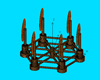 |
Figure 7 DMF grid division. |
Ocean environmental loads mainly include wind, wave and current. In AQWA simulation, for the application of wind and current, first, calculate the up-wind and up-current area of the wind power fishery structure, establish the corresponding wind force coefficient table, and then apply the wind speed and direction. Waves are directly applied to the structure by setting different wave heights and periods.
5 Results and analysis
5.1 Model accuracy verification
In order to verify the accuracy of the hydrodynamic model established in this article, we compared the free attenuation motion simulation and experimental test results of the OC4 floating structure. The accuracy of the model was determined by the amplitude errors of the pitch and roll responses in the time domain. The initial inclination angle is 8° and the initial horizontal displacement is 20 m. This method can not only determine the natural frequency of the platform but also verify the reliability of the numerical solver in solving the hydrodynamic problems of floating structures. The simulation results of free attenuation are obtained as shown in Figures 8 and 9.
 |
Figure 8 Free attenuation of pitching. |
 |
Figure 9 Free attenuation of swaying. |
According to the numerical simulation results in Figures 8 and 9, the prediction of the natural period and attenuation amplitude of the solution model established by AQWA is consistent with Cheng Ping’s numerical simulation of the aerodynamic hydrodynamic coupling flow field of floating wind turbine and OC4 pool test data The maximum error is less than 5%, which proves that the solver has good reliability and accuracy in calculating the hydrodynamic problem of the floating wind turbine support platform. Based on AQWA, the pitch natural period of OC4 is 26.1 s, which is consistent with the 25.8 s calculated by naoe-FOAM-SJTU and the 26.8 s period obtained by the OC4 pool test to verify the accuracy of the model.
5.2 Multi-factor dynamic response analysis
Based on the reliability of the OC4 model, the hydrodynamic response laws of DMF and OC4 are further analyzed based on the same modeling method, including time-domain simulation analysis under single-factor environmental load conditions of wind, wave, and current.
1) Wind action analysis results
In this research, 6 identical wind turbines were used with NREL standard reference rated power of 5MW. Therefore, referring to the corresponding relationship between power generation and Wind float of the 5 MW wind turbine generator, 800 kN equivalent average aerodynamic load of a single wind turbine generator is applied on the tower of wind turbine generator, and the action height is 100 m above the datum plane of waterline. OC4 model is a single wind turbine system with an aerodynamic load of 800 kN, and the direction is 0° positive direction of the X axis. The dot matrix foundation is six wind turbine systems with an aerodynamic load of 4800 kN, and the application direction is the same as that of OC4 Wind float. The mooring system is a three-point catenary mooring with the same parameters. Set the time step to 0.2 s and the duration to 500 s. The dynamic response law of Wind float to DMF and OC4 floating foundation shown in Figure 10 is determined through time domain analysis.
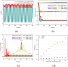 |
Figure 10 Motion response under Wind float. (a) Rocking time domain analysis results (b) oscillation time domain analysis results (c) Mooring tension results (d) Relationship between wind speed and pitch. |
According to Figure 10a, the difference in pitch motion response amplitude between DMF and OC4 is the most obvious in the six degrees of freedom motion response. The maximum amplitudes of DMF and OC4 are −1.2° and −7.8° respectively, and the pitch stability of DMF is improved by 76%. Figure 10b shows that DMF and OC4 also have large amplitude differences in the response of swaying motion. Within 0–100 s, due to the initial horizontal load and mooring action, the horizontal displacement of DMF and OC4 foundation is close to −23 m. In particular, the return displacement of DMF foundation in 25–60 s is about 3 times that of OC4, because of the difference of 6 times wind force in D horizontal direction. It is further verified that the relationship between force and displacement of floating structure in Formulas (7) and (8) is based on the time-domain variation law of mooring tension in Figure 10c. The motion response and mooring tension of the two show a regular periodic small amplitude variation law, and the motion and tension amplitudes of the two are relatively consistent at 100–500 s. Because pitch is the most obvious difference in the six self-degree responses. Figure 10d further obtains the influence law of different wind speeds on DMF and OC4 pitch angle. Both of them show an increasing trend with the increase in wind speed, but the increased range of DMF is much smaller than OC4, which further verifies the stability and superiority of DMF pitch response
2) Wave action analysis results
Waves have a great impact on traditional offshore platform equipment. This part studies the motion response law of the point array foundation under the action of waves. Set the average wave parameters under normal operation conditions in China offshore, with a wave height of 5.49 m and period of 11.3 s, set the regular wave input mode, the direction of X-axis 0°, a time step of 0.2 s, and duration of 500 s. The results are shown in Figure 11.
 |
Figure 11 Motion response under wave load. (a) Oscillation; (b) Mooring tension. |
Figure 11a shows that in terms of displacement motion, the amplitude of sway and heave response of DMF is greater than that of OC4 foundation motion response. DMF is mainly affected by the wave surface displacement due to the large wave surface displacement. Figure 11b shows that the results of the maximum tension of DMF and OC4 under wave action are similar, which is in line with the variation law of mooring tension.
3) Analysis results of flow load
Compared with wind and wave, ocean current has no obvious influence on floating bodies with small draft. With reference to the conventional operation conditions in China’s offshore, the wave current velocity is set to be 0.39 m/s, and the basin range is all water depths. According to the input mode of uniform flow rate, the direction is 0° of the X-axis, the time step is 0.2 s, and the duration is 500 s. The time domain simulation analysis results of DMF and OC4 are shown in Figure 11.
As shown in Figure 12, under the action of a single factor of ocean current, the pitch, roll, and yaw of OC4 and DMF are less than 1°, and the pitch angle is more stable than that under the action of wind and wave. In terms of displacement oscillation, since the load generated by ocean current is less than that of wind and wave, the swaying amplitude and mooring tension are also significantly lower than that of wind and wave.
 |
Figure 12 Motion response under current load. (a) Rocking; (b) Oscillation; (c) Mooring tension. |
The difference in pitch and sway amplitude between DMF and OC4 is the largest by comparing the influence of three single-factor environments of wind, wave, and current on the motion response of DMF. Among them, the pitch stability of DMF under Wind float is obviously superior to that of conventional OC4 foundation. DMF is prone to greater sway horizontal displacement under wave load. The motion response law and amplitude results of the two are consistent.
Since the actual marine environment is mostly the combined action effect of wind, wave and current, based on the previous study of the single-factor action of wind, wave, and current, the motion response analysis of DMF under the combined marine load should be further carried out to clarify the adaptability of the new lattice foundation under the actual marine environmental load.
4) “Wind + Wave + Current” analysis results
The motion response analysis of DMF under the combined environment of wind and current is the simulation closest to the actual marine conditions. Based on the previous factor analysis, this part focuses on the adaptability of DMF to complex marine environments. Set the wind parameter as a single wind turbine, and the average aerodynamic load is 800 kN. We set the wave parameters as a wave height of 5.49 m and a period of 11.3 m/s. The wave current velocity is 0.39 m/s, and the basin range is all water depths. According to the input mode of uniform flow rate, the direction is 0° of X-axis, the time step is 0.2 s, and the duration is 500 s. The time domain simulation analysis results of DMF and OC4 are shown in Figure 13.
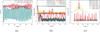 |
Figure 13 “Wind + Wave + Current” joint motion response. (a) Rocking; (b) Oscillation; (c) Mooring tension. |
Figure 13a shows that under the combined action of wind, wave, and current under normal operating conditions, the pitch response amplitudes of DMF and OC4 show periodic fluctuation law. The pitch amplitude of DMF is ±2°, and the pitch amplitude of OC4 is 0.5° to −8.5°. The solution results demonstrate the superiority of the new lattice foundation structure in pitch motion response. Figures 13b and 13c show that the amplitude of the sway response of DMF is significantly higher than that of the conventional OC4 foundation platform. Because the material parameters of the DMF and OC4 mooring systems are the same, the tension of the DMF under the combined action of six wind turbines is four times higher than that of a single OC4 wind turbine.
5.3 Frequency domain analysis
The frequency domain analysis of the new DMF foundation is carried out in the wave frequency range of 0.1–2.1 Hz. The wave height is 1 m. Due to the symmetry of the foundation, the wave direction is 0–180° and the interval is 30°.
Additional mass and radiation damping are important parameters of hydrodynamic characteristics of floating bodies, which are used to characterize the mass and damping changes of floating bodies under the action of fluid. Through frequency domain analysis, we get the added mass and radiation damping of each degree of freedom foundation of DMF, as shown in Figures 14 and 15 respectively. Considering the symmetry of the foundation, Figures 14 and 15 show the additional mass and radiation-damping results of surge and sway, pitch, and roll.
 |
Figure 14 Added mass of DMF. (a) Added mass in surge, sway, and heave; (b) Added mass in roll, pitch, and yaw. |
 |
Figure 15 Radiation damping of DMF. (a) Radiation damping in surge, sway, and heave; (b) Radiation damping in roll, pitch, and yaw. |
Figure 14 shows that the changing trend of the added mass in the surge direction and the yaw direction is roughly the same, and the maximum value of the added mass in the surge direction at the frequency of 1.0 Hz. The added mass in the yaw direction reaches the maximum value when the frequency is 0.9 Hz.
Figure 15 shows that the variation trend of the radiation damping in the surge direction and the Yaw direction is roughly the same, and the radiation damping in the surge direction reaches the maximum near the frequency of 1.1 Hz. The radiation damping in the Yaw direction reaches the maximum value near the frequency of 1.1 Hz.
The motion response amplitude RAO represents the motion of the floating body. Figure 16 shows RAO of DMF in heave, heave, and pitch degrees of freedom obtained through frequency domain simulation analysis.
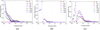 |
Figure 16 RAO of DMF. (a) RAO in surge; (b) RAO in heave; (c) RAO in pitch. |
Due to the symmetry of the DMF structure, the wave incident direction has a great influence on the motion response in the surge direction. At the same wave frequency, the −90° wave downward surge response value is the smallest, and the RAO gradually decreases with the increase of the wave frequency. The heave motion response is basically not affected by the wave incident direction, reaching a peak value between 0.32 Hz and 0.35 Hz. When the wave frequency exceeds 1.5 Hz, the heave motion response approaches zero. The motion response in pitch direction is greatly affected by the wave incident direction. The pitch response in −90° wave direction is the smallest, and the pitch response in 0° and −180° direction is the most intense, with the maximum value between 0.3 Hz and 0.6–0.75 Hz.
6 Experimental model and test
In order to further determine the accuracy of the DMF model and the natural frequency of structure. This study further carried out the prototype processing of the new lattice wind turbine system model and the wave current flume simulation experiment. The hydrodynamic response law of DMF is verified by a self-attenuation test and wind wave hydrodynamic test.
6.1 Model similarity ratio and parameter determination
In order to further verify the accuracy and distribution of the hydrodynamic results of the DMF structure. This article further establishes a small model water tank wave current experiment based on similarity ratio. To ensure the similarity accuracy between the small model and the actual structure, the principle of Reynolds number similarity should be followed when designing the reduction ratio. The scale shall be carried out according to the scale ratio, and the test model shall be processed and manufactured at the ratio of 1:200. Some physical parameters are converted in proportion. The proportional relationship between the physical parameters of the model and the actual components is shown in Table 3. Where subscript s is the actual parameter and subscript m is the model parameter. In Table 3, γ(γ = 1) is the water density ratio of the test model to the actual. λb (λb = gT2/2π) is the wavelength.
proportional relationship of physical parameters.
6.2 DMF test prototype
The processing of the DMF small-scale model prototype is based on the similarity ratio data of physical parameters, and the structural safety strength is fully considered on the premise of ensuring the tightness of the model structure. The main frame material of the model is FRP (Fiber Reinforced Plastics), which can meet the requirements of structural size and buoyancy balance. The main frame and mesh coat of the wind turbine are made of polyethylene. The overall structural quality is adjusted by the counterweight of the weight block to adjust the position of the waterline. The accuracy of the weight and center of gravity position of the model is ensured through the balancing test in the pool. The model of the DMF integrated device is shown in Figure 17.
 |
Figure 17 Small model diagram of DMF test. |
6.3 Test conditions and measuring equipment
The model test was carried out in the towing tank of the hydrodynamic Laboratory of China University of Petroleum (East China). The wave-making system is located at the head end of the pool, and the corresponding wave elimination system is equipped at the tail end to reduce the impact of the wave reflection effect. The wave-making plate is a hollow box plate with a wave-making period of 0.5–5 s and a frequency of 0.6–2 Hz. Under the standard water depth of 1 m, it can produce a wave with a height of 0.35 m and a wavelength in the range of 0.6–20 m. During the test, the test model is arranged at the rear of the water tank to ensure the regularity and accuracy of waves and facilitate the arrangement of sensors and the collection and output of information data.
6.4 Comparison of free attenuation results
The accuracy of the DMF model is verified by hydrostatic free attenuation test and numerical simulation results. The pitch, roll and yaw tests with an initial inclination of 15° and the surge, roll, and heave tests with an initial offset of 0.1 M are carried out on the experimental and simulated DMF models respectively. The results are shown in Figure 18.
 |
Figure 18 Test equipment. |
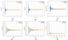 |
Figure 19 Hydrostatic attenuation test and simulation results of six degrees of freedom. (a) Rolling; (b) Pitching; (c) Heaving; (d) Swaying; (e) Surging; (f) Yawing. |
According to the simulation and test results, the six degrees of freedom operation response of DMF shows good recovery stability, and the test results are relatively consistent. The specific data are shown in Table 3. The maximum error is less than 10%, which verifies the accuracy and reliability of the model. The test values are greater than the simulation values, mainly because the simulation does not consider the viscous damping response. The response amplitudes of rolling, pitching, and heating three degrees of freedom detect the structural stability and natural frequency characteristics of DMF. Swaying, surging, and yawing three degrees of freedom detect the periodic response of DMF in a mooring state. The reason for the large difference in response period compared with rolling, pitching, and heating is mainly related to the mooring length and preload of catenary. It does not affect the accuracy verification of the model.
Carry out flume test under wind wave current environmental load. The reliability of the model is further verified by comparing it with the hydrodynamic analysis results of the simulation model. Refer to Table 4 similarity ratio criteria to determine the input wind wave current load parameters. The wave height is 0.027 m, the period is 0.799 s, the regular wave input mode is adopted, the wind speed is 0.81 m/s, and the current velocity is 0.028 m/s. The three load directions are the positive direction of the X-axis. Figure 20 shows the time domain hydrodynamic response results of heave and pitch.
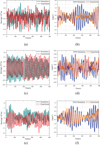 |
Figure 20 Wind wave current load test results. (a) Heaving of “wind + wave”; (b) Pitching of “wind + wave”; (c) Heaving of “wave + current”; (d) Pitching of “wave + current”; (e) Heaving of “wind + wave + current”; (f) Pitching of “wind + wave + current”. |
Natural period of DMF.
We extend the experiment of the hydrodynamic response of the new DMF under actual wind and wave loads. Through the hydrostatic free attenuation test, “wind + wave”, “wave + current” and “wind + wave + current” are three common actual marine environmental load tests. The agreement between the experimental and simulated data based on wind, wave, and current environmental loads is weaker than the free attenuation test results. But the overall error is less than 10%. The reliability of the model is established through a free attenuation test and hydrodynamic response test under regular environmental load.
7 Design and analysis of DMF system stability optimization scheme
Based on the above analysis and research, the new DMF maintains good system stability in pitch, roll, and yaw. However, DMF is worse than OC4 in response to control of sway motion. Because the motion response of a floating foundation is mainly affected by its own structure and mooring system, the traditional catenary mooring method cannot achieve good stability control results for DMF. Therefore, this part studies the influence of different mooring optimization schemes on the motion stability of DMF.
Figure 21 shows the optimization scheme of the DMF mooring system, and the traditional catenary mooring system is shown in C. In this paper, it is considered to optimize the sway stability of DMF by changing the layout and length of the mooring system. As shown in Figure 21, the mooring system is arranged asymmetrically, and the mooring length on the windward side is reduced to improve the initial tension and control effect of mooring. The leeward side shortens the anchor distance and reduces the rolling recovery distance.
 |
Figure 21 DMF mooring optimization scheme. |
In order to better describe the mooring line shape and mechanical balance relationship in Figure 21. We revised Figure 21 DMF moving optimization scheme. In addition, we also added the equation of motion of mechanical equilibrium. Please refer to Formulas (17), (18), and (19) in the paper. The mooring forces of scheme A in Figure 21 are FA1 and FA2. Formula (17) is satisfied under the action of environmental load Fi. Take the floating body at rest on the water surface as an example. At this time, the moving speed of the floating body is 0 m/s, and the right side of the equal sign in Formula (17) is 0. At this time, the mooring forces FA1, FA2, and the environmental load Fi satisfy Formulas (18) and (19). The shape of A is determined according to the principle of mechanical balance and the magnitude of environmental load.![Mathematical equation: $$ {F}_i+{F}_{A2}-{F}_{A1}=\frac{1}{2}{C}_d{\rho }_w{lD}\left[u(t)-x(t)\right]|u(t)-x(t)| $$](/articles/stet/full_html/2023/01/stet20220122/stet20220122-eq20.gif) (17)
(17)
 (18)
(18)
 (19)
(19)
Based on this scheme, the DMF mooring parameters are modified to obtain the time-domain motion response results, as shown in Figure 22.
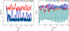 |
Figure 22 Comparison results of motion stability. (a) Sway response amplitude; (b) Pitch response amplitude. |
The maximum mooring line tension obtained in the optimized configuration of this article is 6.53 × 10⁷ N, much smaller than the before optimization of 9.96 × 10⁷ N, therefore the optimization effect is good to adapt to the DMF structure scheme. Figure 22 shows the motion response amplitude of the mooring system (DMF(O)) after DMF optimization and the relationship between OC4 and DMF. The swaying amplitude of DMF(O) is between −7 m and 3 m, and the swaying amplitude of DMF is between −22 m and −3 m. The overall drift stability is improved by 47%. The pitch amplitude of DMF(O) is between −3° and 0.7°, and the pitch amplitude of DMF is between −2° and 1.5°. The pitch stability is basically unchanged. It is obvious from Figure 22a that the optimized DMF mooring scheme has significantly improved the overall motion stability. Therefore, the optimization method of the mooring system has certain guiding and reference significance.
8 Conclusion
In this study, a new concept of a dot matrix multi-wind turbine combined integrated system is proposed. The feasibility and superiority of the scheme are verified by structural parameter analysis and numerical model test. The main results can be summarized as follows:
-
The new DMF scheme forms an integrated power generation system through a dot matrix arrangement, which provides the possibility for the research and development of higher power offshore power generation equipment. The design scheme of the wind power fishery integrated development system is established to realize the integrated application of marine aquaculture and wind energy development, which provides a new model and new idea for the development of far-reaching marine wind power energy combination equipment in the future.
-
The initial stability mechanical model of DMF considering waterline and moment of inertia is established, which is based on the particularity of a dot matrix foundation structure. Compared with the traditional wind tilt moment stability equation, the DMF stability balance equation more intuitively establishes the relationship between the parameters of the floating structure and the initial stability of pitch. This paper provides a method convenient for the comparison and verification of hydrodynamic stability law between the theoretical model and numerical simulation and provides a new method and idea for the research and analysis of stability law in the conceptual design stage of a new floating structure.
-
Considering the multi-factor environmental effect of wind, wave, and current, the aerodynamic hydrodynamic simulation and experimental test of DMF are carried out, which shows that the pitching stability of DMF is better than that of traditional OC4. Under the influence of different environmental loads, the pitching stability of DMF is about 70% higher than that of traditional OC4. This conclusion also demonstrates the accuracy and feasibility of the initial stability mechanical model of Formula (7) based on the waterline surface and moment of inertia in this study.
-
In order to further verify the accuracy of the DMF model and the natural frequency of the structure. This study further carried out the prototype processing of the new lattice wind turbine system model and the wave flow tank simulation experiment. Through the self-attenuation test, the data are in good agreement with the simulation results. Because the viscous damping and eddy current effect of water are not considered in the simulation, the response amplitude data is slightly larger than the experimental results, and the error is less than 5%, which does not affect the accuracy verification of the results.
-
Because the point array infrastructure adopts the form of six wind turbines, the horizontal Wind float is six times larger than the traditional single wind turbine power generation system. Therefore, under the action of traditional catenary mooring, greater horizontal sway displacement is inevitable. In this paper, under the same environmental parameters, it is concluded that the swaying amplitude of DMF is three times that of OC4 response. In order to improve the six degrees of freedom overall stability and operation safety of the point array wind turbine system, the optimal design of the mooring system is further considered in this study. By comprehensively adjusting the mooring arrangement angle, direction, length relationship, and other factors, on the basis of not affecting the pitch and swing stability of DMF, the sway response amplitude is reduced by 47%, which obviously optimizes the system stability and marine environment adaptability.
Many challenges related to the feasibility of wind power fishery systems still exist, and further research is needed to develop a robust concept for practical deployment. It includes the optimization of the layout scheme of six wind turbines, the impact of long-term fatigue analysis, the possible wave impact effect, the effective survival strategy under extreme sea conditions, and the optimal design of the new combined system. Research on these aspects should be incorporated into future research.
Acknowledgments
The support for this research is gratefully acknowledged by the China University of Petroleum (East China) Marine Engineering Experiment Center and Qingdao West Coast Science and Technology innovation project “Research on Key Technologies of Marine Fishery Electricity Integrated Development System (2019-8)”.
CRediT authorship contribution
Jiangfeng ZHU, Yuguang CAO: Conceptualization, Methodology, Software, Writing – original draft. Chenyi REN: Funding acquisition, Supervision. Yuanyuan LIU, Qiankun ZHAO: Validation, Writing – review and editing.
Conflict of interest
The authors declare that they have no known competing financial interests or personal relationships that could have appeared to influence the work reported in this paper.
Ethical standards
This article does not contain any studies with human participants or animals performed by any of the authors.
Informed consent
Informed consent was obtained from all individual participants included in the study.
Funding
This research did not receive any specific grant from funding agencies in the public, commercial, or not-for-profit sectors.
Data Availability
The Code encapsulating the algorithm described in this paper is open source under the GNU General Public License v3.0. Source code and sample input datasets are available at [30]. The monthly meteorological time series used in the example interpolation is available for download at https://www.ncdc.noaa.gov/cag/national/time-series.
References
- Liu Y., Hu C., Makoto S., Shigeo Y., Hidetsugu I., Masashi K. (2021) Motion response characteristics of a Kyushu-University semi-submersible floating wind turbine with trussed slender structures: experiment vs. numerical simulation. Ocean Eng. 232. ISSN 0029-8018. https://doi.org/10.1016/j.oceaneng.2021.109078. [Google Scholar]
- Aryai V., Abbassi R., Abdussamie N., Salehi F., Garaniya V., Asadnia M., Baksh A.-A., Penesis I., Karampour H., Draper S., Magee A., Keng A.K., Shearer C., Sivandran S., Yew L.K., Cook D., Underwood M., Martini A., Heasman K., Abrahams J., Wang C.-M. (2021) Reliability of multi-purpose offshore-facilities: present status and future direction in Australia, Process. Saf. Environ. Prot. 148, 437–461. https://doi.org/10.1016/j.psep.2020.10.016. [CrossRef] [Google Scholar]
- Laura C., Elson M., Guedes Soares C. (2016) Cost assessment methodology for combined wind and wave floating offshore renewable energy systems, Renewable Energy 97, 866–80. ISSN 0960-1481. https://doi.org/10.1016/j.renene.2016.06.016. [CrossRef] [Google Scholar]
- Robin C., Emmanuel A., Joseph A. (2021) A fleet based surplus production model that accounts for increases in fishing power with application to two West African pelagic stocks, Fish. Res. 243. https://doi.org/10.1016/j.fishres.2021.106048. [Google Scholar]
- Zheng L., Wang S., Cui M. (2022) Modeling and dynamic response analysis of a submersible floating offshore wind turbine integrated with aquaculture cage, Ocean Engineering 263, ISSN 0029-8018. https://doi.org/10.1016/j.oceaneng.2022.112338. [Google Scholar]
- Aquafarms (2020) Hex Box. Available at http://www.oceanaquafarms.com/. [Google Scholar]
- Papandroulakis N., Papaioannou D., Divanach P. (2002) An automated feeding system for intensive hatcheries. Aquac. Eng. 26, 1, 13–26. ISSN 0144-8609. https://doi.org/10.1016/S0144-8609(01)00091-7. [CrossRef] [Google Scholar]
- Zheng X., Zheng H., Lei Y., Li Y., Li W. (2020) An offshore floating wind–solar–aquaculture system: concept design and extreme response in survival conditions, Energies 13, 3, 604–1. https://doi.org/10.3390/en13030604. [CrossRef] [Google Scholar]
- Zhang L., Zhang T., Zhang K. (2023) Research on power fluctuation strategy of hybrid energy storage to suppress wind-photovoltaic hybrid power system, Energy Reports 10, 3166–3173. ISSN 2352-4847. https://doi.org/10.1016/j.egyr.2023.09.176. [CrossRef] [Google Scholar]
- Zhang Y., Song Y., Shen C., Chen N. (2023) Aerodynamic and structural analysis for blades of a 15MW floating offshore wind turbine. Ocean Eng. 287, 1, 115785. ISSN 0029-8018. https://doi.org/10.1016/j.oceaneng.2023.115785. [CrossRef] [Google Scholar]
- Wayman E., Sclavounos P., Butterfield S., Jonkman J., Musial W. (2006) Coupled dynamic modeling of floating wind turbine systems, in:2006 Offshore Technology Conference, 1–4 May 2006, Houston, TX, USA. [Google Scholar]
- Wayman E.N. (2006) Coupled dynamics and economic analysis of floating wind turbine systems. Dissertation, Massachusetts Institute of Technology, Massachusetts, USA. [Google Scholar]
- Ju G., Sweetman B., Tang S.R. (2022) Multiaxial fatigue assessment of floating offshore wind turbine blades operating on compliant floating platforms. Ocean Eng. 261, 111921. ISSN 0029-8018. https://doi.org/10.1016/j.oceaneng.2022.111921. [CrossRef] [Google Scholar]
- Sweetman B., Wang L. (2012) Floating offshore wind turbine dynamics: large-angle motions in euler-space, J. Offshore Mech. Arct. Eng. 134, 1903–1911. [CrossRef] [Google Scholar]
- Wang L., Sweetman B. (2012) Simulation of large- amplitude motion of floating wind turbines using conservation of momentum, Ocean Eng. 42, 155–164. [CrossRef] [Google Scholar]
- Nielsen F.G., Hanson T.D., Skaare B. (2006) Integrated dynamic analysis of floating offshor wind turbines, in: Proceedings of OMAE2006 25th International Conference on Offshore Mechanics and Arctic Engineering, 4–9 June 2006. [Google Scholar]
- Larsen T.J., Hanson T.D. (2007) A method to avoid negative damped low frequent tower vibrations for a floating, pitch controlled wind turbine, J Phys Conf Ser 75, 012073. [CrossRef] [Google Scholar]
- Karimirad M., Moan T. (2010) Extreme structural dynamic response of a SPAR type wind turbine, Trans Mech Eng. 17, 2, 146–156. [Google Scholar]
- Matha D., Fischer T., Kuhn M., Jonkman J. (2009) Model development and loads analysis of a wind turbine on a floating offshore tension leg platform, in: 2009 European Offshore Wind Conference and Exhibition, September, 2009, Stockholm, Sweden. [Google Scholar]
- Adam F., Myland T., Dahlhaus F., Großmann J. (2014) Scale tests of the GICON-TLP for wind turbines, in: Proceedings of the ASME 2014 33rd International Conference on Ocean, Offshore and Arctic Engineering. Volume 9A: Ocean Renewable Energy, San Francisco, California, USA, June 8–13, 2014. V09AT09A011. ASME. https://doi.org/10.1115/OMAE2014-23216. [Google Scholar]
- Uchida T., Gagnon Y. (2022) Effects of continuously changing inlet wind direction on near-to-far wake characteristics behind wind turbines over flat terrain, J. Wind Eng. Ind. Aerodyn. 220, 104869. https://doi.org/10.1016/j.jweia.2021.104869. [CrossRef] [Google Scholar]
- Tian L., Song Y., Xiao P., Zhao N., Shen W., Zhu C. (2022) A new three-dimensional analytical model for wind turbine wake turbulence intensity predictions. Renewable Energy 189, 762–776. ISSN 0960-1481. https://doi.org/10.1016/j.renene.2022.02.115. [CrossRef] [Google Scholar]
- Liu W., Shi J., Chen H., Liu H., Lin Z., Wang L. (2021) Lagrangian actuator model for wind turbine wake aerodynamics, Energy 232, 121074. https://doi.org/10.1016/j.energy.2021.121074. [CrossRef] [Google Scholar]
- Dong G., Li Z., Qin J., Yang X. (2022) Predictive capability of actuator disk models for wakes of different wind turbine designs, Renew. Energy 188, 269–281. https://doi.org/10.1016/j.renene.2022.02.034. [CrossRef] [Google Scholar]
- Lopes A.M.G., Vicente A.H.S.N., Sánchez O.H., Daus R., Koch H. (2022) Operation assessment of analytical wind turbine wake models. J. Wind Eng. Ind. Aerodyn. 220, 104840. ISSN 0167-6105. https://doi.org/10.1016/j.jweia.2021.104840. [CrossRef] [Google Scholar]
- Nakhchi M.E., Win Naung S., Rahmati M. (2022) A novel hybrid control strategy of wind turbine wakes in tandem configuration to improve power production, Energ. Convers. Manage. 260, 115575. https://doi.org/10.1016/j.enconman.2022.115575. [CrossRef] [Google Scholar]
- Jonkman J., Butterfield S., Musial W., Scott G. (2009) Definition of a 5-MW reference wind turbine for offshore system development, Technical Report NREL/TP-500-38060, National Renewable Energy Laboratory, Golden, Colorado, USA. [Google Scholar]
- Api D. (2005) Analysis of station keeping systems for floating structures, API RP 2SK, 3rd edn, American Petroleum Institute, Washington, DC, USA. [Google Scholar]
- Raffaella N., Micaela M., Massimiliano P., Laura P. (2023) Environmental cognitive load and spatial anxiety: What matters in navigation? J. Environ. Psychol. 88, 102032. ISSN 0272-4944. https://doi.org/10.1016/j.jenvp.2023.102032. [CrossRef] [Google Scholar]
- Kaplan J.O., Lai L. ARVE-Research/newspline: First official release. https://doi.org/10.5281/zenodo.5783076. [Google Scholar]
All Tables
All Figures
|
Figure 1 Concept of multi-wind turbine integrated structure. |
| In the text | |
|
Figure 2 Concept of dot matrix floating foundation. |
| In the text | |
|
Figure 3 Dot matrix basic parameter model. |
| In the text | |
|
Figure 4 Mooring system layout scheme. |
| In the text | |
|
Figure 5 Stress model of traditional floating foundation. |
| In the text | |
|
Figure 6 Mechanical model of DMF floating foundation. |
| In the text | |
|
Figure 7 DMF grid division. |
| In the text | |
|
Figure 8 Free attenuation of pitching. |
| In the text | |
|
Figure 9 Free attenuation of swaying. |
| In the text | |
|
Figure 10 Motion response under Wind float. (a) Rocking time domain analysis results (b) oscillation time domain analysis results (c) Mooring tension results (d) Relationship between wind speed and pitch. |
| In the text | |
|
Figure 11 Motion response under wave load. (a) Oscillation; (b) Mooring tension. |
| In the text | |
|
Figure 12 Motion response under current load. (a) Rocking; (b) Oscillation; (c) Mooring tension. |
| In the text | |
|
Figure 13 “Wind + Wave + Current” joint motion response. (a) Rocking; (b) Oscillation; (c) Mooring tension. |
| In the text | |
|
Figure 14 Added mass of DMF. (a) Added mass in surge, sway, and heave; (b) Added mass in roll, pitch, and yaw. |
| In the text | |
|
Figure 15 Radiation damping of DMF. (a) Radiation damping in surge, sway, and heave; (b) Radiation damping in roll, pitch, and yaw. |
| In the text | |
|
Figure 16 RAO of DMF. (a) RAO in surge; (b) RAO in heave; (c) RAO in pitch. |
| In the text | |
|
Figure 17 Small model diagram of DMF test. |
| In the text | |
|
Figure 18 Test equipment. |
| In the text | |
|
Figure 19 Hydrostatic attenuation test and simulation results of six degrees of freedom. (a) Rolling; (b) Pitching; (c) Heaving; (d) Swaying; (e) Surging; (f) Yawing. |
| In the text | |
|
Figure 20 Wind wave current load test results. (a) Heaving of “wind + wave”; (b) Pitching of “wind + wave”; (c) Heaving of “wave + current”; (d) Pitching of “wave + current”; (e) Heaving of “wind + wave + current”; (f) Pitching of “wind + wave + current”. |
| In the text | |
|
Figure 21 DMF mooring optimization scheme. |
| In the text | |
|
Figure 22 Comparison results of motion stability. (a) Sway response amplitude; (b) Pitch response amplitude. |
| In the text | |
Current usage metrics show cumulative count of Article Views (full-text article views including HTML views, PDF and ePub downloads, according to the available data) and Abstracts Views on Vision4Press platform.
Data correspond to usage on the plateform after 2015. The current usage metrics is available 48-96 hours after online publication and is updated daily on week days.
Initial download of the metrics may take a while.